Dynamic rocker back (cont.), Ynamics, Eating – Freedom Designs Freedom NXT User Manual
Page 39: Dynamic rocker back, Freedom designs nxt, 30 freedom designs, inc
30
FREEDOM DESIGNS, INC.
WPCNXT 62013
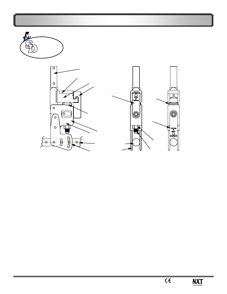
Dynamic Rocker Back (cont.)
Lower Backpost, .740” Dia to fit
1” OD * .120 Wall Aluminum Backcane
Actuator Arm
Latch, shown in locked
postion when wheelchair
is being pushed or
transported.
Impact Cap
Lock Nut
Impact Elastomers Supplied
Soft: Yellow (2)
Med: Clear (2 installed)
Firm: Green (2)
X-Firm: Blue (2)
Rebound
Elastomer (Clear installed)
Dynamic Rocker Back
Installation Instructions For
Freedom Designs NXT
Actuator Rod
Cover Plate
Doc: DRB FDNTX 7/6/2012
Step 1: Remove original back canes and mounting brackets from the wheelchair.
Save back canes & hardware for reuse, discard original mounting brackets, they are not required with DRB.
Step 2: Install DRB assembly on to the seat frame as shown above by aligning the mounting adapters to the appropriate
holes in the frame for the seat depth required. Use original Freedom supplied 1/4” bolts, nuts and flat washers, 3 per side.
Make certain that there is a flat washer between the bolt / nut and the DRB mounting adapters.
Step 2a: The NXT has flat surfaces machined on the sides of the seat frame tube. Tighten the bolts and nuts to securely clamp
the DRB mounting adapters to the seat frame. Seat to back angle adjustment is easily made by loosening the 2 forward bolts
and removing the rear most bolt. Seat to back angle may adjusted to plus/minus 18° degrees in 6° increments. Securely tighten
all bolts after making adjustments.
Step 3: Shorten the NXT back canes by approximately 7.5”, cutting the bottom of the tube to maintain the desired back height. Your cut
should be 1/2” or slightly less below the center of a hole in order for the back cane holes to line up with the holes in the DRB lower
backpost. Remember, measure twice, cut once!
Step 4: Place the back canes over the DRB lower backpost and secure with the two bolts supplied with the DRB.
Step 5: Install or reinstall any seating as required.
Step 1: Remove the Lock Nut and flat washer from the Acutator Rod. The Rebound Elastomer may fall out of the pocket. Open the Latch.
Step 2: Remove the 5mm socket head screws securing the cover plate of the actuator arm. At this point, lift the actuator rod up, removing
it from the housing. The back is now free to fold forward, exposing the impact elastomer and pocket.
Step 3: Remove the Impact Elastomer, remove the Impact Cap from the top of the Impact Elastomer and install on to the new Impact Elastomer.
Step 4: Place the new Impact Elastomer into the pocket, return the back to an upright position, place the actuator rod throught the actuator
arm and elastomer. Place the Rebound Elastomer into its pocket, over the actuator rod. Return the Latch to the closed / latched position.
Install and tighten the Lock Nut until it compresses the Rebound Elastomer so that the Latch operates freely.
Step 5: Reinstall the Cover on to the Actuator Arm. Tighten the screws and check to make sure the latch swings freely and engages in the detent
of the actuator arm. If it does not operate freely, adjust the Lock Nut as required, when properly adjusted you should be able to see a
small amount of daylight between the interlocking surfaces of the Latch and Actuator Arm.
To Replace or Change Elastomers:
Additional tools required: 4mm Allen Wrench, 3/4” Open End Wrench
Latch, shown in
unlocked postion
to allow dynamic
rocking by user.
Housing
American Track Roadsters, Inc. 1500 W. Hampden Ave. # 3-C Englewood, CO 80110 303-986-9300 f 303-986-9301
Wheelchair Frame Tube
DRB Mounting Adapters
(4 ea. 3/16” thick req’d, 1 ea inside
and outside of frame per side of chair)
ynamics
D
S
eating
Front of
Wheelchair,
LH
Outside
Shown
ynamics
D
S
eating
We have a new name!
We make wheelchairs better.
Tools Required: 3/16 Allen Wrench, 7/16 wrench or socket (Freedom hardware only)
5mm Allen Wrench, 10mm wrench or socket (Seating Dynamics hardware is metric)
Hacksaw, file or deburring tool.