Bio-Rad BioLogic QuadTec™ Detector and Components User Manual
Page 24
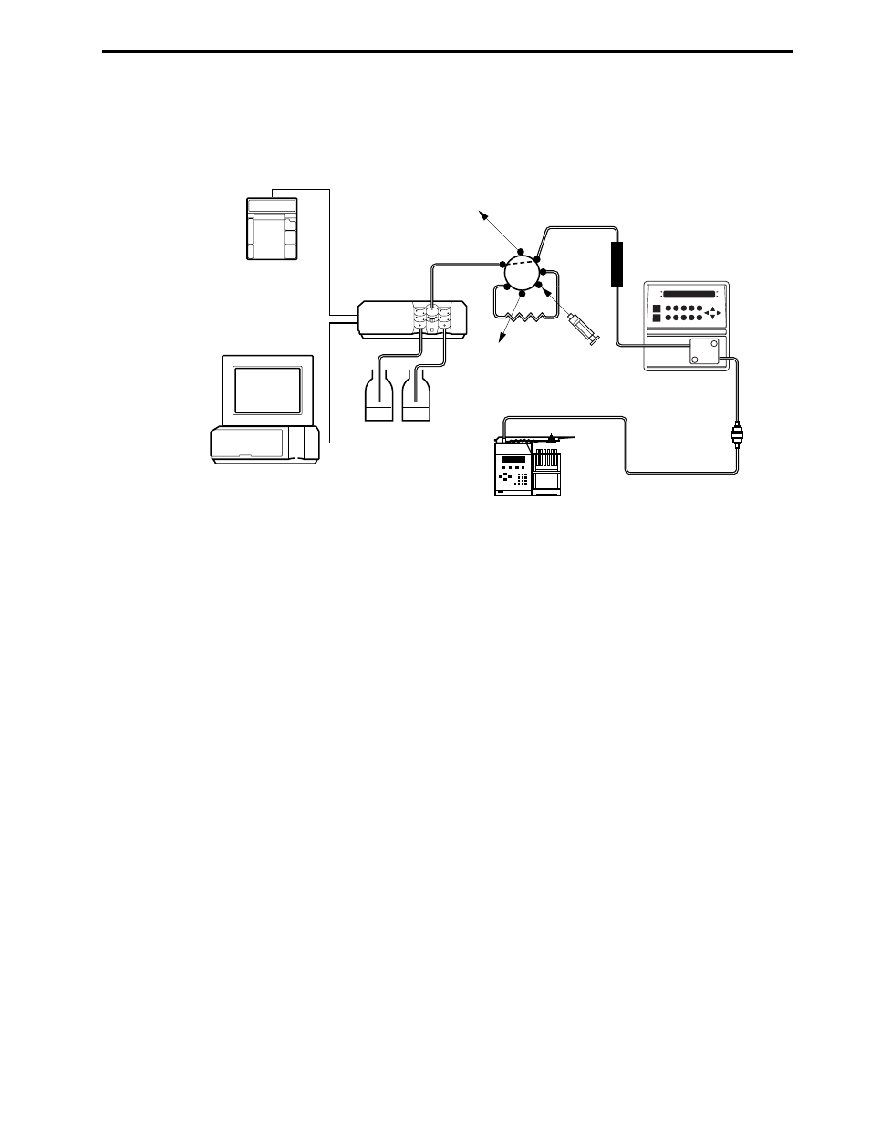
3.2 PLUMBING CONNECTIONS TO THE BIOLOGIC HR SYSTEM
After making all the cable connections make the plumbing connections, as shown in Figure 3-3.
Figure 3-3. Plumbing to the BioLogic HR System
3.3 SYSTEM OPERATION WITH THE BIOLOGIC HR
Each time the QuadTec is powered on, it runs a self test. If successful, the lamp warms up to a constant
working temperature. During warm up, the display shows HEA in the lower left position. The initialization
routine is completed by an automatic calibration procedure, and the device is ready for operation when ON
is shown in the lower left position.
3.3.1 Using the QuadTec Faceplate Keys
The following QuadTec front panel keys and displays are used:
•
Arrow keys: The green, arrow-shaped keys are used for moving and positioning the cursor in the
display and for confirming an entered value.
•
Numeric keys: The blue, numeric keys 1 to 0 are used for entering numeric values at the position
of the cursor.
•
Auto zero: When pressed for less than 2 seconds, this key performs an auto-zero over the whole
wavelength range. This feature is required for use with the BioLogic HR system and in stand-alone
mode. With the BioLogic DuoFlow, zero baseline commands are sent from the Controller.
USE WITH THE BIOLOGIC HR SYSTEM
SYSTEM INSTALLATION AND SETUP
3-3
1
2
3
4
5
6
7
A
B
WORKSTATION
CHART
RECORDER
V7-3 or AV7-3
INJECT VALVE
BUFFER A and B
WASTE
CONTROLLER
AND COLOR
MONITOR
INJECT
PORT RINSE
WASTE
INSTRUMENT BUS
COLLECT TO
MODEL 2128
FRACTION
COLLECTOR
COLUMN
QUADTEC
DETECTOR
CONDUCTIVITY
MONITOR