Bio-Rad BioLogic QuadTec™ Detector and Components User Manual
Page 23
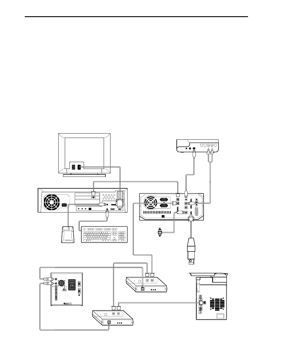
3.1 ELECTRICAL CONNECTIONS TO THE BIOLOGIC HR SYSTEM
Set up the BioLogic HR system with the QuadTec detector on the bottom tray. Do not turn power on.
1.
Connect one SIM-HR to the HR Workstation with System Cable 17, and ensure that the SIM’s
device address number (Device Number) is set to 1.
2.
"Daisy-chain" a second SIM-HR to the first SIM-HR using a second System Cable 17. The device
address number (Device Number) of this second SIM-HR must be set to 0.
3.
Connect the QuadTec to the SIM-HR modules using two System Cable 24, an analog cable that has
red and black bare wires at one end and a gold colored banana plug at the other. Plug the banana
plugs into the 1V Integrator sockets on the rear of the QuadTec marked 1 and 2. The cable in socket
1 should go to the first SIM-HR (Device Number 1) and the cable in socket 2 goes to the second
SIM-HR (Device Number 0). In both cases the cable red wire goes to the analog + connector and
the black wire to the analog - connector of the SIM-HR.
4.
If a Model 2128 Fraction Collector is to be used, connect it to SIM 2 using System Cable 17.
Figure 3-2. Connections to the BioLogic HR System
USE WITH THE BIOLOGIC HR SYSTEM
SYSTEM INSTALLATION AND SETUP
3-2
WORKSTATION
MODEL 2128
FRACTION
COLLECTOR
SIM 2 (ADDRESS 0)
SIM 1 (ADDRESS 1)
MODEL 1327
CHART RECORDER
SYSTEM CABLE 17
SYSTEM
CABLE 17
SYSTEM CABLE 24
SYSTEM CABLE 24
SYSTEM
CABLE 2
AV7-3
AUTOMATED
INJECT VALVE
CONDUCTIVITY
MONITOR
SYSTEM
CABLE 17
SYSTEM
CABLE 4
QUADTEC
DETECTOR
COLOR MONITOR
SYSTEM CABLE 17
CONTROLLER
KEYBOARD
MOUSE