3 gel doc xr system cable configuration, Connecting the cabling harnesses – Bio-Rad Gel Doc™ XR+ System User Manual
Page 20
20
4.3.3 Gel Doc XR System Cable Configuration
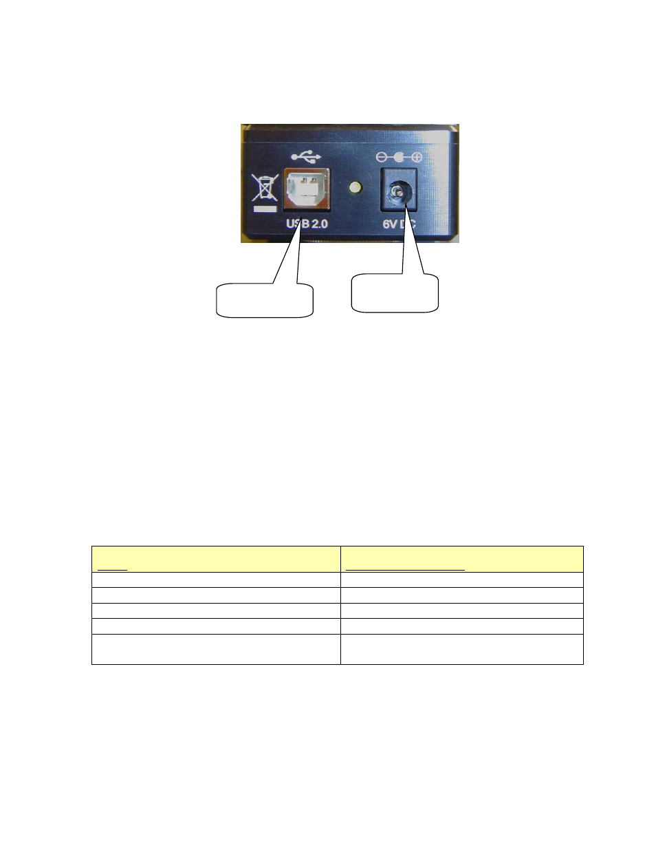
Camera connections
Connecting the cabling harnesses
1. Locate the 6 ft USB cable. Connect one end of the USB cable connector to the USB port on the
camera. Connect the other end to the corresponding port on the rear panel on the Universal
Hood that says ‘TO CAMERA’.
2. The camera power supply cable should be plugged into the CCD camera power connector.
3. Connect the MZL (Motorized Zoom Lens, page 13) cable connector to the connector labeled
LENS
on the rear panel of the Universal Hood.
4. Connect the 10 ft USB cable from the Universal Hood to the PC.
5. The main power cable that connects the Universal Hood to the power outlet.
The following table describes the cable/connectors and their designations.
Label
Instrument/Connection
10 ft USB connector/cable
From hood to PC
6 ft USB connector/cable
From camera to hood
Camera power supply cord/power supply
Camera/PWR connector
MZL (motorized zoom lens) cable
Hood/LENS Din connector
Power cable
Connects the Hood to the power outlet on
the wall
See the cabling diagram on the following page.
Power supply
connector
USB connector