Bio-Rad PDS-1000 / He™ and Hepta™ Systems User Manual
Page 29
Screw the rupture disk retaining cap onto the gas acceleration tube using a left -to-right
motion. Never tighten the rupture disk retaining cap without a rupture disk in place or scratch-
ing and deformation of the two metal surfaces will occur and cause helium to leak when a rup-
ture disk is pressurized.
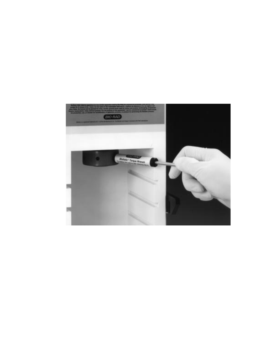
The retaining cap is tightened to a torque of 60 inch/pounds with the retaining cap torque
wrench. To use the torque wrench, insert the short end of the metal rod into an accessible hole
in the retaining cap. Push the long end of the rod to the right only until it touches the inner sur-
face of the black tube (Figure 4.8). If the retaining cap is not tightened sufficiently, the rupture
disk may slip out of place as the gas acceleration tube fills with helium. Test fire once to fill gas
tubing with helium.
Fig. 4.8. Proper torque applied to retaining cap with torque wrench.
8. Microcarrier Launch Assembly
Unscrew the macrocarrier cover lid from the assembly. Place a sterile stopping screen on the
stopping screen support (Figure 4.9). Note: Never operate the PDS-1000/He instrument without
a stopping screen in place. The target sample will be destroyed from the uninterrupted acceleration
of the macrocarrier by the helium shock wave.
Install the macrocarrier/macrocarrier holder on the top rim of the fixed nest (Figure 4.10).
The dried microcarriers should be facing down, toward the stopping screen. Replace the
macrocarrier cover lid on the assembly and turn clockwise until snug. Do not over-tighten.
Place the microcarrier launch assembly in the top slot inside the bombardment chamber
(Figures 4.11 and 5.1).
26
➡
➥