Connect opener lift hoses – Great Plains 3S-3000HDF Predelivery Manual User Manual
Page 15
Assembly 13
12/09/2009
195-068Q
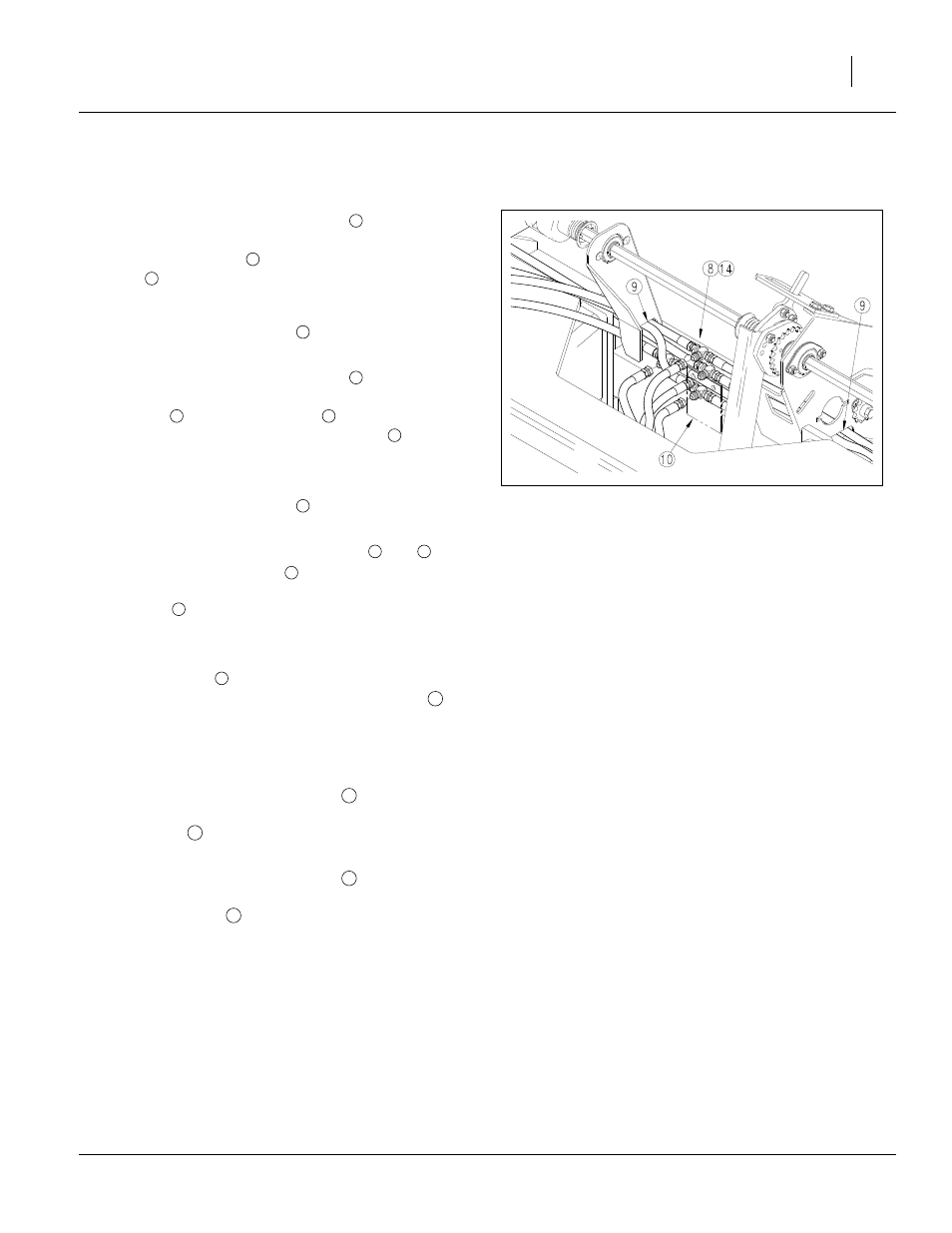
Connect Opener Lift Hoses
Refer to Figure 8 on page 14
22. Connect the
3
⁄
8
in hydraulic hoses
coming from
the back side of the wing pressure control valve to
the base end tees
on the inner opener lift cylin-
der
of each wing frame.
This is the hose which should extend beyond the
wing tool bar hose holder
by 45in (1.1m) as
assembled from the factory.
23. Connect the
3
⁄
8
in hydraulic hoses
coming from
the bottom of the wing pressure control valve, to
the tee
at the jumper hose
coming from the
rod end of the inner opener lift cylinder
of each
wing frame.
This is the hose which should extend beyond the
wing tool bar hose holder
by 35in (89cm) as
assembled from the factory.
24. Disconnect the
3
⁄
8
in hydraulic hoses
and
where they tee together
at the back of the main-
frame and reroute them through the hose guide
cutouts
and through the plastic tie downs on the
center box frame.
Refer to Figure 7
25. Place all tees
which rest on the center box
frame on the right side of the formed bracket
welded to the center of the frame.
This keeps them out of the clutch linkage which is
left of center.
26. Connect the
3
⁄
8
in hydraulic hose
coming from
the back side of the center pressure control valve
to the tee
which branches to the base ends of
the center two opener lift cylinders.
27. Connect the
3
⁄
8
in hydraulic hose
coming from
the bottom side of the center pressure control
valve to the tee
which branches to the rod ends
of the center two opener lift cylinders.
28. Tighten the plastic tie down straps to keep the
hoses out of the drives.
Figure 7
Opener Lift Tees
15656
1
2
3
4
5
6
7
3
4
1
5
8
9
8
10
11
12
13
14