Great Plains UT5052 Operator Manual User Manual
Page 27
Great Plains Mfg., Inc.
Section 1: Assembly
10/28/2004
Series I UT3030-UT5052 Ultra-Till 576-026M
25
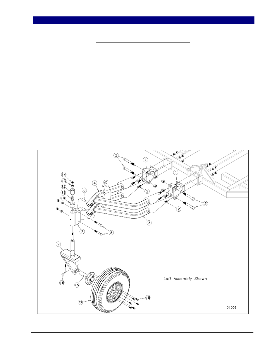
Hydraulic Gauge Wheel Assembly
On models UT5042, UT5048 &
UT5052, bolt the gauge wheel arm mount
clevis (1) to the front bar of wing brace as
shown in Figure 12 using the 5/8 x 1 1/2 hex
bolts (2), lock washers and hex nuts. Insert the
linkage arms (3) and (4) into the arm clevis
(1). Assemble with 1 x 6 hex bolt (5) and
nylon lock nut. Do not torque down. Insert
the clamp bushings (6) into the front of the
linkage arms (3) and (4). Bolt the pivot bracket
(7) to the arms as shown with 3/4 x 4 1/2 hex
bolt (8) using lock washer and hex nuts. Insert
the appropriate left or right gauge wheel arm
(9) into the pivot bracket (7) and install the
friction cap (10), spring (11), spring cover
(12), 3/4” hex nut (13) and 3/4” jam nut (14)
to secure the assembly. Insert the hub and
spindle assembly (15) into the gauge wheel
arm (9), using anti-seize material on the
spindle. Secure with 5/16 x 3 clevis pin (16)
and 1/8 x 1 cotter. Bolt on the rim and tire
assembly (17) with six 1/2 x 1 1/4 lug bolts
(18). Install the gauge wheel hydraulic
cylinders (or ratchet jacks) as per hydraulic
layout for your machine, Section 2. Use 1 x 8
1/2 eye-bolts with 1” jam nuts at the base of
the cylinders. For directions on the proper
setting for the hydraulic gauge wheel during
operation, refer to Section 4 Operating and
Maintenance.
Figure 12
4/5/2007