Great Plains UT5052 Operator Manual User Manual
Page 20
Section 1: Assembly
Great Plains Mfg., Inc.
Series I UT3030-UT5052 Ultra-Till 576-026M
10/28/2004
18
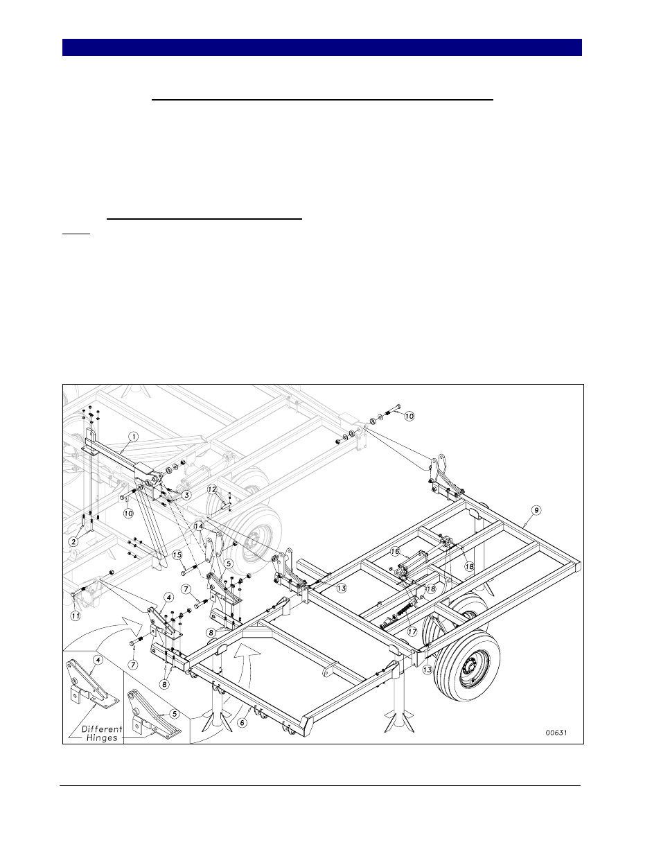
Connecting Outside Wing and Wing Brace Assembly
On models UT5042, UT5048 &
UT5052, bolt the auxiliary fold bracket (1) to
the inside wing brace with two 5/8 x 3 x 5 1/2
u-bolts (2) and four 5/8 x 1 1/2 hex bolts (3)
using lock washers and hex nuts, see Figure 5.
Bolt the outside wing fold hinges (4) and (5) as
shown, (Note: Hinges (4) and (5) are not the
same) to the outside wing brace (6) with 1 x
5½ hex bolts (7) and 5/8 x 3 x 5 1/2 u-bolts (8)
using lock washers and hex nuts.
On all 5-section models, bolt the outside
wing brace (6) to the plates on the outside wing
(9) with 3/4 x 2 hex bolts (13), with lock
washers and hex nuts. Bolt and pin the outside
wing assembly to the inside wing frame with 1
x 7 GR 8 hex bolts (10), with rollers and flat
washers and 1 x 6 Gr.8 hex bolt (11) and 1 x 5
hardened pin (12). Securing bolts with 1” nylon
lock nuts and the 1 x 5 pin (12) with 3/8 x 2 1/4
GR 8 hex bolt and lock nut.
On models UT5042, UT5048 &
UT5052, bolt the two rockers (14) (as shown)
to the wing fold hinge (5) with 1 x 7 Gr.8
special thread hex bolt (15). Secure with Nylon
lock nut.
Attach the outside rephasing lift
cylinder (16) (See hydraulics in parts manual
for proper cylinder sizes) between the lever on
the wheel bracket and the 1 1/4 x 9 1/2 eye bolt
(17) in the wing bracket. Use 1 x 3½ clevis
pins (18) with 1” machine washer and 3/16 x 2
cotter pins and 1 1/4 ” jam nuts on the eye-bolt.
Figure 5
4/11/2005