Great Plains UT5052 Operator Manual User Manual
Page 17
Great Plains Mfg., Inc.
Section 1: Assembly
10/28/2004
Series I UT3030-UT5052 Ultra-Till 576-026M
15
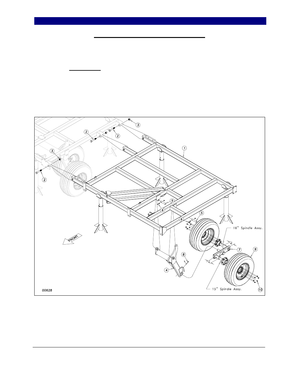
Inside Wing and Wheel Arm Assembly
Bolt the inside wing frames (1) Figure
2, to the center frame with three 1 x 6 hex bolts
(2) with nylon lock nuts (3). Draw the nuts
down tight but do not torque.
Once the wings are attached, insert the
wheel arm bracket (4) into the wing frame
hangers and secure it just as you did on the
center with 1¼ x 6 pins (5). Secure the pins
with 3/8 x 2 1/4 Gr.8 hex bolts (6) & top lock
nuts.
Install the wing walking beam assembly
(7) as shown in Figure 2 with the short 15
spindle toward the front. Use anti-seize
material on spindle. Secure the pivot spindle in
the sleeve with the 5/16 x 3 clevis pin (8) and
1/8 x 1 cotter.
Bolt the 11L x 15, 8-ply tire (9) in place
with the 9/16” lug nuts (10).
Figure 2
10/31/2005