Great Plains UT5052 Operator Manual User Manual
Page 19
Great Plains Mfg., Inc.
Section 1: Assembly
10/28/2004
Series I UT3030-UT5052 Ultra-Till 576-026M
17
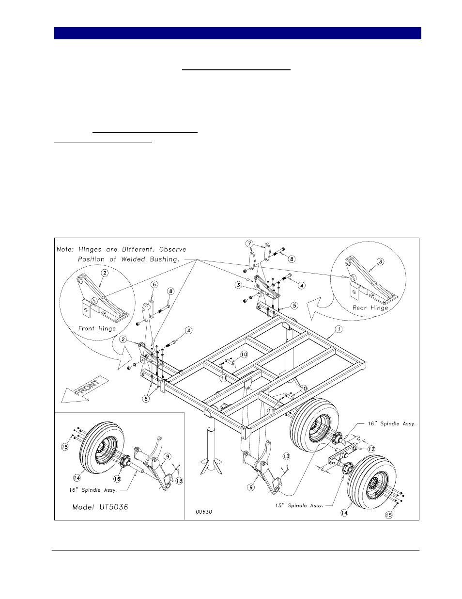
Outside Wing Assembly
On 5-section models, preassemble the
outside wing (1) by attaching the outside hinges
(2) and (3) to the wing with 1 x 6 hex bolt (4)
and 5/8 x 3 x 5 1/2 u-bolts (5) as shown in
Figure 4 (Note: hinges (2) and (3) are
different from each other). Use a nylon lock
nut on the 1 x 6 hex bolt (4) with lock washers
and hex nuts on the u-bolts (5). Attach the Fold
H-Bracket (6), bulge side in and up, to the front
hinge with the 1 x 7 Gr.8 special thread hex
bolt (8). Attach the two Rocker (7) to the rear
hinge, bulge side out and up, with the same 1 x
7 Gr.8 special thread hex bolt (8). Use 1” nylon
lock nuts on these bolts.
Attach the outside wheel bracket (9) just
as we did the inside ones, using the 1 1/4 x 6
pins (10) and 3/8 x 2 1/4 Gr.8 hex bolts (11) &
lock nuts. Slide the walking beam assembly
(12) into the wheel bracket sleeve as shown in
Figure 4. Again, it is recommended to use
some form of anti-seize product on the spindle.
Secure with 5/16 x 3 clevis pin (13) and 1/8 x
1” cotter pin. Note that the shorter 15” long
spindle assembly goes to the front. Bolt on the
11L x 15 tire and wheels (14) with the 9/16”
lug nuts (15).
Model UT5036 uses one 11L x 15 tire
and a 16” Hub & Spindle assembly (16) as
shown in insert.
Figure 4
10/31/2005