Great Plains UT5052 Operator Manual User Manual
Page 23
Great Plains Mfg., Inc.
Section 1: Assembly
10/28/2004
Series I UT3030-UT5052 Ultra-Till 576-026M
21
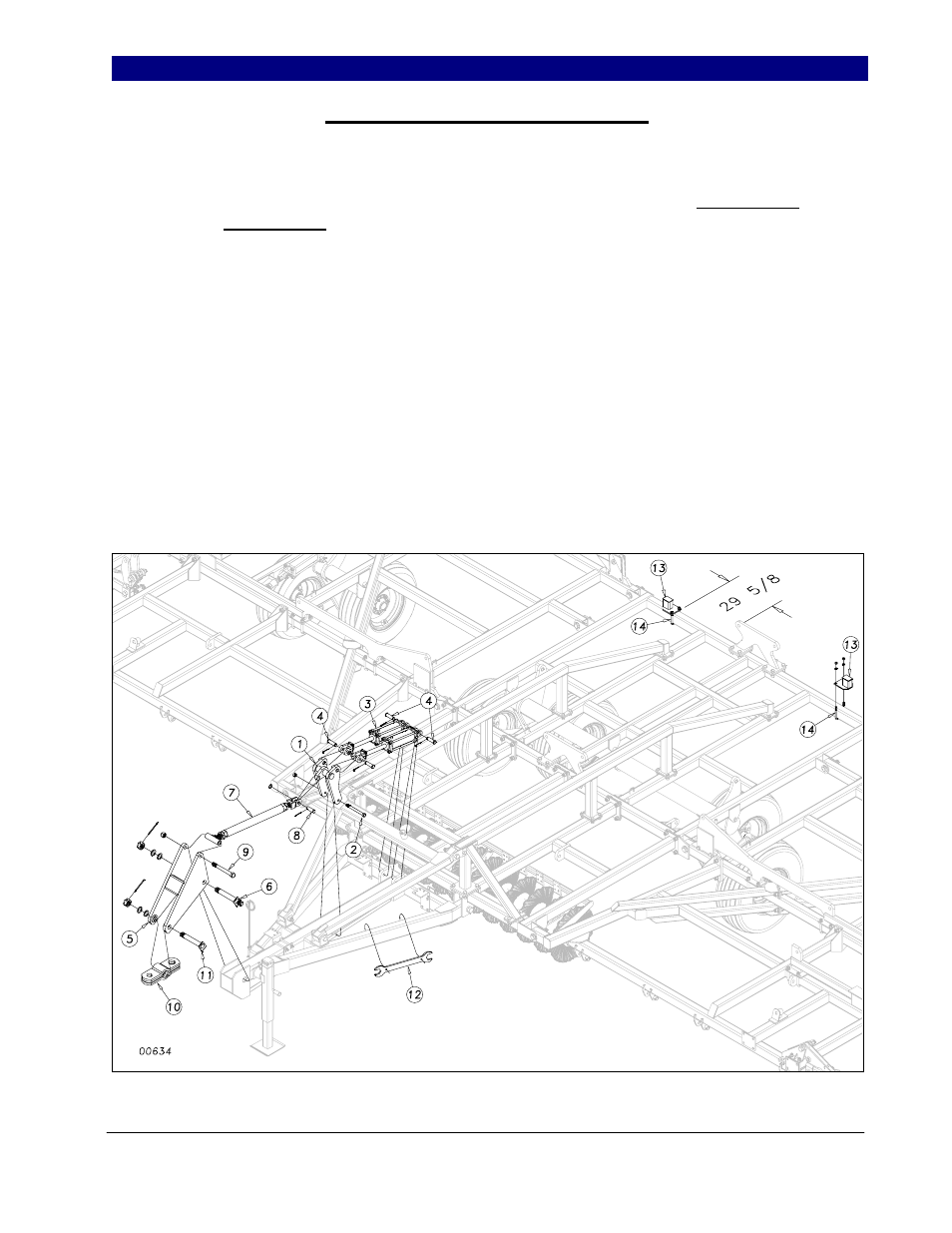
Self Level and Rest Pads Assembly
Slide the H-bracket (1) down over the
hitch pole as shown in Figure 8. Bolt in place
with a 3/4 x 8 bolt (2) and 3/4” lock nut. Draw
this nut up but do not torque, as this part must
pivot. Pin the self leveling rephasing cylinders
(3) to the hitch and H-bracket (1) with 1” x 3
1/2” clevis pins (4), machine washers and 3/16
x 2 cotter pins (see Hydraulics in parts manual
for proper size of cylinders).
Slide the side plate weldment (5) over
the end of the hitch and bolt in place as shown
with the 1 1/2 x 12 safety chain hitch bolt (6).
Secure with 1½ slotted hex nut and 1/4 x 3
cotter pin. Use the 1½ machine washers as
needed for proper fit. Connect the turnbuckle
(7) between the side plate assembly (5) and the
H-bracket (1). Use a 1 x 3 3/8 usable clevis pin
(8) with machine washer and 3/16 x 2 cotter pin
at the back end of turnbuckle. Use a 1 x 9 Gr.8
bolt (9) with a nylon lock nut at the tee end of
the turnbuckle. Snug, but do not torque nylon
lock nut.
Insert the hitch clevis (10) into the front
of the side plate weldment (5) and bolt in place
with a 1 1/2 x 9 3/8 hitch bolt (11). Secure
with slotted hex nut, machine washers and 1/4
x 3 cotter pin, using the 1½ machine washers
again as needed for proper fit.
Install the turnbuckle wrench (12) on
the storage pins of the hitch weldment.
On 5-section models, u-bolt the cylinder
rest pads (13) to the back bar of the center
frame using a 1/2 x 3 x 5 u-bolt (14) with lock
washers and hex nuts. Place the edge of the
rest pads (13) 29 5/8” out from the hole in the
fold bracket as shown.
Figure 8