Install gauge wheel, Install k-flex, Install gauge wheel install k-flex – Great Plains 8560 FCF Assembly Manual User Manual
Page 20
16
8323-8560FCC
Great Plains Manufacturing, Inc.
560-483Q-ENG
02/10/2014
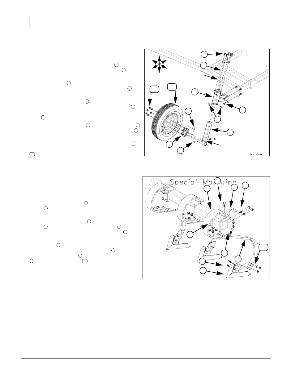
Install Gauge Wheel
94. Start by installing the wheel arm mount
to the
plates on wing frame with 5/8 x 2 hex bolts
, 5/8
lock washers and 5/8 nuts.
95. Slide screw jack
down through the wheel arm
mount plate, secure with 1/2 x 1 1/4 hex bolts
and
1/2 top lock nuts
96. Slide the spindle receiver
inside the wheel arm
mount, align holes, secure with 3/4 x 4 hex bolt
, 3/
4 lock washer and 3/4 nut. Install two 5/8 x 1 1/4 hex
bolts
to welded nuts on wheel arm mount.
97. Slide 6-bolt hub assembly
into spindle receiver
,
align holes, secure with 5/16 x 2 13/16 clevis pin
and 1/8 x 1 cotter pin.
98. Attach the 9.5L x 15, 8 ply, wheel/tire assembly
to
6-bolt hub assembly and secure with 9/16 lug nuts
.
99. Tighten bolts to specs, See “Torque Values Chart”
Install K-Flex
Note: See layout section in appendix section for proper
shank placement.
Refer to Figure 18
100.Slide k-flex shank mount
through slot in k-flex
clamp
. Slide these two parts over frame tube in
proper location.
101.Align top hole in k-flex clip
with top hole in k-flex
clamp
, secure with 1/2 x 1 1/2 hex bolt
, 1/2 lock
washer and 1/2 nut. Install 1/2 x 5 hex bolts
, 1/2
lock washers and 1/2 nuts.
102.Slide shank
through slotted hole in k-flex shank
mount (1), secure with 5/8 x 2 hex bolt
and 5/8 top
lock nut. Attach sweep
with 7/16 x 1 3/4 plow bolts
, one, 7/16 flat washer
(top slotted hole) and 7/
16 nylock nuts.
103.Tighten all bolts to specs, See “Torque Values
Figure 17
Gauge Wheel Assembly
41881
U
D
F
B
L
R
1
2
6
7
5
9
8
Align Hole
Align Hole
10
11
3
4
1
2
3
4
5
6
7
8
5
9
10
11
Figure 18
K-Flex Assembly
41667
7
6
1
3
4
5
2
10
8
9
1
2
3
2
4
5
6
7
8
9
10