Assembly, Install center frame – Great Plains 8560 FCF Assembly Manual User Manual
Page 12
560-483Q-ENG
02/10/2014
8
8323-8560FCC
Great Plains Manufacturing, Inc.
Assembly
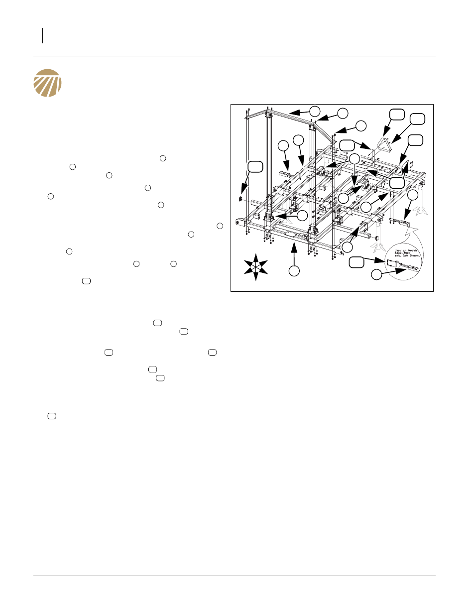
Install Center Frame
Once the center Frame has been uncrated and put
on stands, the brace bar and trusses maybe
installed.
4.
Carefully move center brace bar
to front of center
frame
, with overhead hoist or fork lift, secure with
3/4 x 2 hex bolts
, 3/4 lock washers and 3/4 nuts.
5.
Attach center frame trusses
with 3/4 x 2 hex bolts
(front plates), 3/4 lock washers and 3/4 nuts, rear
plates with 5/8 x 1 1/2 hex bolts
, 5/8 lock washers
and 5/8 nuts.
6.
On models 8332-8560 attach the brace bar truss
(middle plates) with 5/8 x 1 1/2 hex bolts
, 5/8 lock
washers and 5/8 nuts, outside plates with 3/4 x 2 hex
bolts
, 3/4 lock washers and 3/4 nuts.
7.
Attach light brackets, LH
and RH
with 1/2 x 3 1/
32 x 6 u-bolts (models 8323-8328) or 1/2 x 5 1/32 x 4
1/2 u-bolt
(models 8332-8560), 1/2 lock washers
and 1/2 nuts.
Note: See machine layout section in this manual for prop-
er light bracket placement.
8.
Attach light mounting brackets
to rear center
frame tube with 1/2 x 4 1/32 x 4 u-bolt
, 1/2 lock
washers and 1/2 nuts.
9.
Mount smv post
with 1/2 x 4 1/32 x 4 u-bolt
, 1/
2 lock washers and 1/2 nuts as close to center of
tube shown. Attach smv sign
to rear of smv post
with 1/4 x 3/4 pan head screws
, 1/4 lock washers
and nuts.
10. All bolts may be tightened to specs, See “Torque
Values Chart” on page 25. Attach plastic end caps
to all open ends of 4 x 3 tube.
Figure 5
Center Frame Assembly
41884
7
1
5
6
7
3
16
8
2
3
4
14 15
12
9
11
13
5
3
10
U
D
F
B
L
R
2
1
3
4
3
5
6
5
3
7
8
10
11
12
13
12
14
15
16