Install 5-section wing, Install 5-section wing fold, Install 5-section wing install 5-section wing fold – Great Plains 8560 FCF Assembly Manual User Manual
Page 17
Great Plains Manufacturing, Inc.
Assembly
13
02/10/2014
560-483Q-ENG
Install 5-Section Wing
Refer to Figure 12
Note: Be sure and install the 1 x 6 1/4 hinge pins
as shown
with roll pin in slot on front side of hinge.
60. Carefully align holes in wing frame LH
with holes in
center frame. Secure with 1 1/4 x 6 1/4 hinge pins
, 3/
8 x 2 1/2 roll pins, 1 flat washer 1 top lock nut.
61. Attach wing brace
to the front of the wing frame LH
with 3/4 x 2 hex bolts
, 3/4 lock washers and 3/4 hex
nuts.
62. Align holes in wheel arm L
, secure with 1 1/4 x 6 pins
, 3/8 x 2 1/4 hex bolts and 3/8 top lock nuts.
63. Fasten LH wing truss
to wing with 5/8 x 1 1/2 hex
bolts
, 5/8 lock washers and 5/8 hex nuts.
64. Attach base end of 3.50 x 8 x 1.25 lift cylinder (models
8539-8548) or 3.75 x 8 x 1.38 lift cylinder (models 8551-
8560)
to front hole of cylinder mount plate
with 1 x
3 1/8 pin
, 1.5 x 1.0 x.075 machine washer and 3/16 x
2 cotter pin. Attach rod end of cylinder
to wheel arm L
with 1 x 3 1/8 pin
, 1.5 x 1.0 x.075 machine washer
and 3/16 x 2 cotter pin.
65. Tighten all bolts to specs, See “Torque Values Chart”
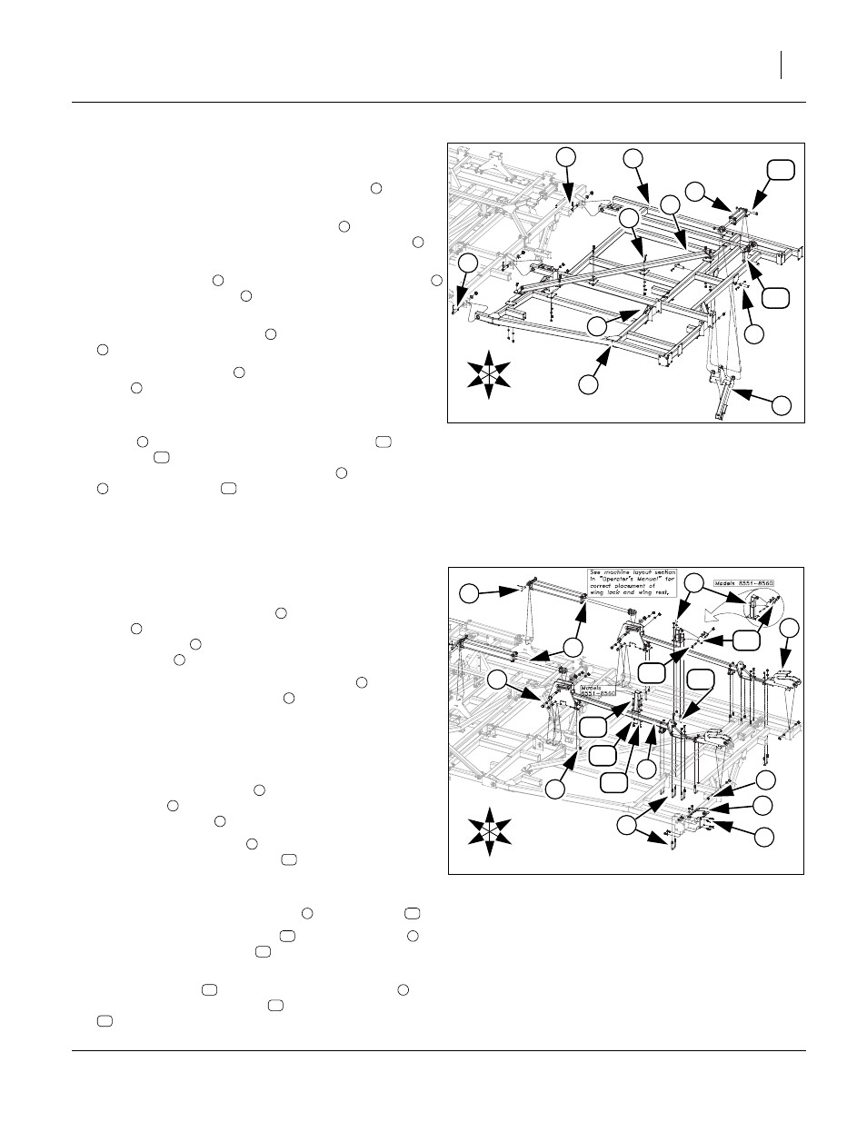
Install 5-Section Wing Fold
Refer to Figure 13
66. Mount wing folding brackets
to wing with 3/4 x 5 hex
bolts
, 3/4 lock washers and 3/4 hex nuts, 5/8 x 3 1/32
x 5 1/2 u-bolts
5/8 lock washers and 5/8 nuts, 3/4 x 5
1/2 hex bolt
, 3/4 lock washer and 3/4 nut.
67. Attach base end of 4 x 30 x 1.5 cylinders
to center
fold bracket with 1 x 3 1/8 pin
, 1.5 x 1.0 x.075
machine washer and 3/16 x 2 cotter pin.
68. Do not attach rod end of fold cylinders until fold system
has been purged, See “Purging Hydraulic System” on
page 22.
69. Attach inside wing hinge
to wing brace with 5/8 x 1 1/
2 hex bolts
, 5/8 lock washers and 5/8 hex nuts, 5/8 x 3
1/32 x 5 1/2 u-bolt
, 5/8 lock washers and 5/8 nuts.
70. Attach wing lock mount
, on top of wing frame tube,
with 1/28 x 3 1/32 x 5 u-bolts
, 5/8 lock washers and
5/8 nuts.
Note: See layout section in “Operator’s Manual” for proper
placement of wing lock mount
and wing rest
.
71. Bolt the automatic wing latch
, wing lock mount
,
with 3/4 x 4 1/2 hex bolts
, 3/4 lock washers and 3/
4 nuts.
72. Attach wing rest
to front wing folding bracket
,
secure with wing rest plate
, 1/2 x 4 1/2 hex bolts
, 1/2 lock washers and 1/2 nuts.
73. Tighten all bolts to specs, See “Torque Values
74. Repeat same procedure for right wing.
Figure 12
5-Section Wing Assembly
41894
1
4
11
3
U
D
F
B
L
R
10
2
5
2
8
7
6
9
2
1
2
3
1
4
5
6
7
8
9
10
11
9
5
11
Figure 13
5-Section Wing Fold Assembly
41895
1
11
3
U
D
F
B
L
R
2
4
5
9
8
7
3
1
6
10
12
14
13
15
1
2
3
4
5
6
7
8
3
9
10
9
13
11
9
12
13
1
14
15