Torque tube & level bar, Center fold, Torque tube & level bar center fold – Great Plains 8560 FCF Assembly Manual User Manual
Page 13
Great Plains Manufacturing, Inc.
Assembly
9
02/10/2014
560-483Q-ENG
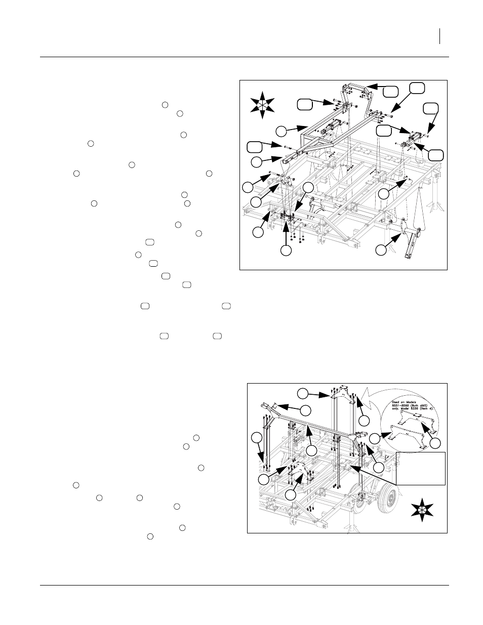
Torque Tube & Level Bar
Refer to Figure 6
11. Carefully raise the torque tube
with an overhead
hoist and secure with 1 1/4 x 6 pins
, 3/8 x 2 1/4 Gr.
8 hex bolts and 3/8 top lock nut.
12. Attach the h-bracket mounting plate
with 3/4 x 2
hex bolts
, secure with 3/4 lock washers and 3/4
nuts
13. Attach the h- bracket
into the h-bracket mounting
plate
, secure with 1 x 2 29/64 clevis pins
, 1.5
machine washers and 3/16 x 2 cotter pins.
14. Attach level bar slide tube assembly
to top hole of
h- bracket
with 1 x 9 Gr. 8 hex bolt
and 1 top
lock nut.
15. Now slide the front of the level bar
over the back
side of the level bar slide tube assembly
, secure
with a 3/4 x 5 1/2 hex bolt
and 3/4 lock nut.
16. Attach rear of level bar
to the torque tube with the
1 x 6 Gr. 8 special hex bolt
and 1 top lock nut.
17. Mount the level bar cross tube
to the level bar
side plates with 5/8 x 1 1/2 hex bolts
, secure with
5/8 lock washers and 5/8 nuts.
18. Now install the cylinders
using 1 x 3 1/8 pins
,
1.5 x 1.0 x.075 machine washers and 3/16 x 2 cotter
pin.
19. Install cylinder transport locks
to cylinders
using 3/8 x 3 pins and clip pins.
20. All bolts may be tightened to specs, See “Torque
Center Fold
Refer to Figure 7
Note: Models 8323-8328 wing stop goes on rear plates of
center frame trusses. All other models go on front
plates as shown.
21. Attach inside plates of center wing stop
, to center
frame trusses using 5/8 x 1 1/2 bolts
, 5/8 lock
washers and nuts.
22. Attach outside plates of center wing stop
, to out-
side tubes of center frame with 5/8 x 3 1/32 x 6 1/2 u-
bolts
, 5/8 lock washers and nuts.
23. Mount front
and rear
fold brackets to center
frame plates with 5/8 x 1 1/2 bolts
, 5/8 lock wash-
ers and nuts.
24. Insert the 1/2 x 4 1/2 pin w/keepers
into round
tubes on rear of wing stop
.
25. All bolts may be tightened to specs, See “Torque
Figure 6
Torque Tube & Level Bar Assembly
41885
1
9
4
5
3
12
11
16
2
15
14
7
6
13
U
D
F
B
L
R
8
10
1
2
3
4
5
3
6
7
5
8
9
7
10
9
11
12
13
14
15
16
14
Figure 7
Center Fold Assembly
41886
5
1
4
5
4
2
6
2
U
D
F
B
L
R
2
3
Models 8323-
8328 Go On
Rear Plates
of Trusses.
1
2
1
3
4
5
2
6
1