Connect hitch, Install wing cylinder mount, Connect hitch install wing cylinder mount – Great Plains 8560 FCF Assembly Manual User Manual
Page 14
10
8323-8560FCC
Great Plains Manufacturing, Inc.
560-483Q-ENG
02/10/2014
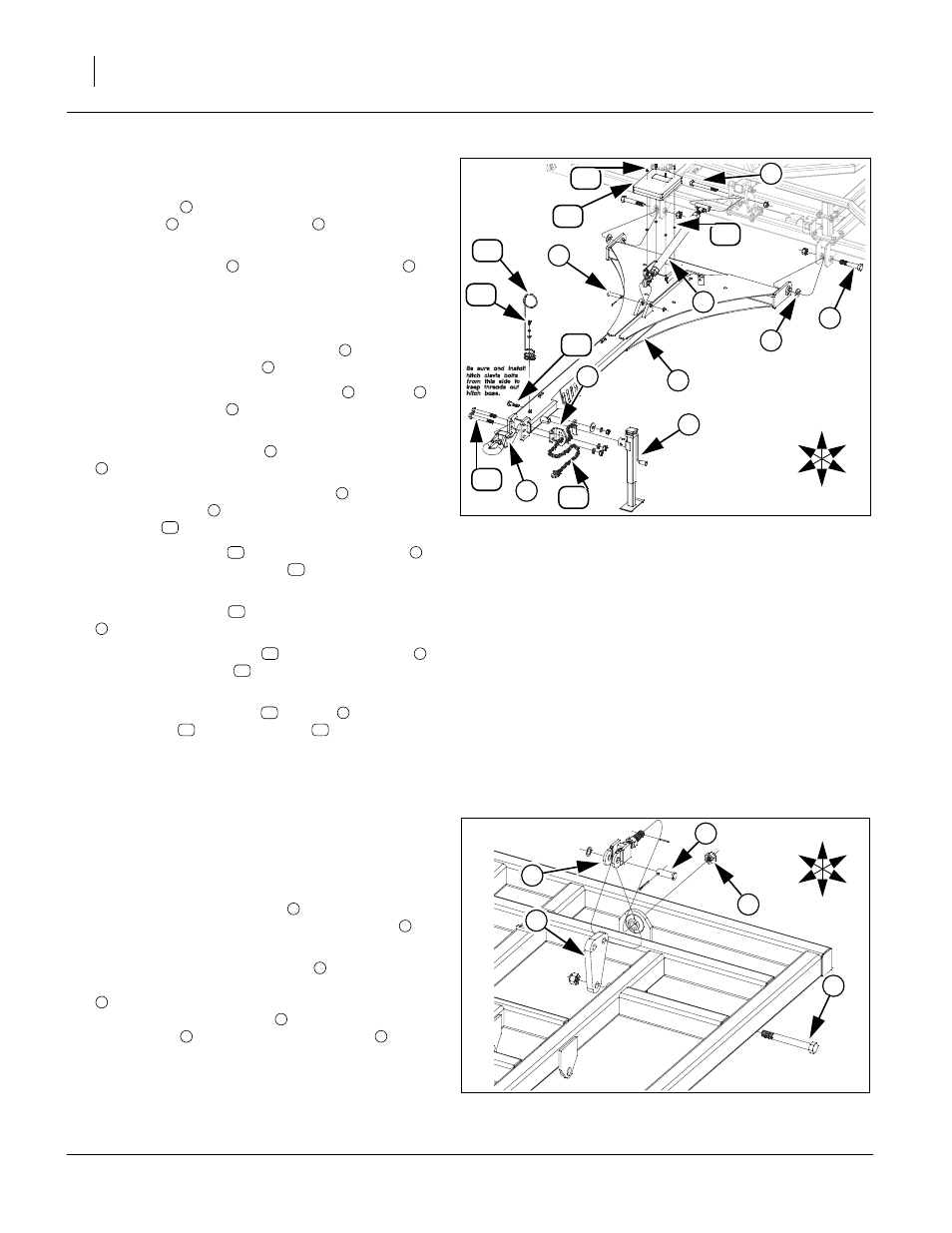
Connect Hitch
Refer to Figure 8
26. Attach hitch
to center brace bar using 1 1/4 x 7 Gr.
8 hex bolt
, 1 1/4 flat washers
(one on outside of
hitch, both sides) and top lock nut.
27. Mount square jack
to front mount on hitch
with
pin provided with jack.
Note: Use jack to help support front of hitch for rest of
hitch assembly.
28. Attach rear of turnbuckle assembly
to h-bracket
with 1 x 9 Gr. 8 hex bolt
and 1 nylon lock nut.
29. Attach front of turnbuckle assembly
to hitch
using 1 x 4 1/2 pin
, 1.5 x 1.0 x.075 machine
washer and 3/16 x 2 cotter pin.
30. Align holes in hitch base
with holes in front of hitch
.
31. Align holes in safety chain support
with holes on
left side of hitch
, secure with 1 x 8 Gr. 8 special
hex bolts
, 1 lock washers and 1 nuts.
32. Install safety chain
on bottom side of hitch
,
secure with 7/8 x 3 hex bolt
, 7/8 flat washer, 7/8
lock washer and 7/8 nut.
33. Route safety chain
through safety chain support
.
34. Mount spring hose loop
to top side of hitch
,
with 1/2 x 1 1/2 bolt
, 1/2 lock washer and 1/2 flat
washer.
35. Mount the manual pack
to hitch
with 1/4 x 3/4
pan screws
, rubber spacers
, 1/4 lock washers
and 1/4 nuts.
36. All bolts may be tightened to specs, See “Torque
Install Wing Cylinder Mount
Refer to Figure 9
Note: The wing cylinder mount assemblies will be in-
stalled as shown below for all wings.
37. Attach cylinder mount plate
to inside of tube weld-
ment of wing frame, with 1 x 9 Gr. 8 hex bolt
and 1
top lock nut. Tighten bolt down snug.
38. Slide adjustment bolt assembly
through front side
of ball joint on wing frame, secure with 1 slotted nut
and 3/16 x 1 1/2 roll pin. Attach clevis end of
adjustment bolt assembly
to rear hole of cylinder
mount plate
with 1 x 2 29/64 clevis pin
, 1.5 x 1.0
x.075 machine washer and 3/16 x 2 cotter pin.
Note: See side to side leveling in “Operator’s Manual” for
proper adjustment of wing when machine is com-
pletely assembled.
Figure 8
Hitch Assembly
41888
1
6
9
7
17
4
3
16
U
D
F
B
L
R
15
2
8
12
14
13
5
10
11
1
2
3
4
1
5
6
5
1
7
8
1
9
1
10
11
1
12
11
8
13
1
14
15
1
16
17
Figure 9
Wing Cylinder Mount Assembly
41919
5
1
3
U
D
F
B
L
R
2
4
1
2
3
4
3
1
5