Install 8323 & 8328 wings – Great Plains 8560 FCF Assembly Manual User Manual
Page 15
Great Plains Manufacturing, Inc.
Assembly
11
02/10/2014
560-483Q-ENG
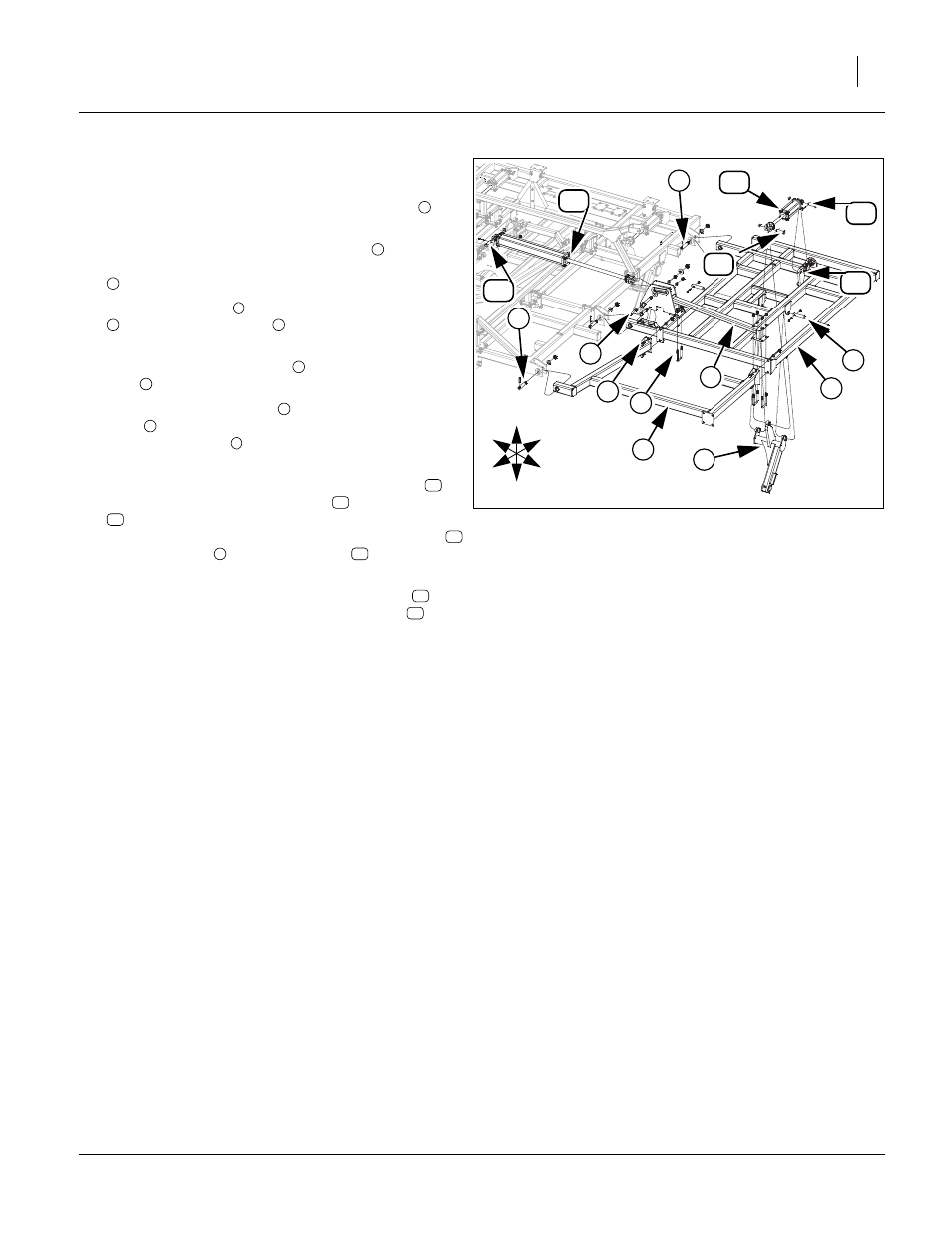
Install 8323 & 8328 Wings
Refer to Figure 10
Note: Be sure and install the 1 x 6 1/4 hinge pins
as
shown with roll pin in slot on front side of hinge.
39. Carefully align holes in wing frame LH
with holes
in center frame. Secure with 1 1/4 x 6 1/4 hinge pins
, 3/8 x 2 1/2 roll pins, 1 flat washer 1 top lock nut.
40. Attach wing brace
to the front of the wing frame LH
with 3/4 x 2 hex bolts
, 3/4 lock washers and 3/4
hex nuts.
41. Align holes in wheel arm L
, secure with 1 1/4 x 6
pins
, 3/8 x 2 1/4 hex bolts and 3/8 top lock nuts.
42. Mount wing fold bracket
to wing with 3/4 x 5 hex
bolts
, 3/4 lock washers and 3/4 hex nuts, 5/8 x 3 1/
32 x 5 1/2 u-bolts
, 5/8 lock washers and 5/8 hex
nuts.
43. Attach base end of 3.25 x 8 x 1.25 lift cylinder
to
front hole of cylinder mount plate
with 1 x 3 1/8 pin
, 1.5 x 1.0 x.075 machine washer and 3/16 x 2 cot-
ter pin. Attach rod end of 3.25 x 8 x 1.25 cylinder
to wheel arm L
with 1 x 3 1/8 pin
, 1.5 x 1.0
x.075 machine washer and 3/16 x 2 cotter pin.
44. Attach base end of 4 x 30 x 1.5 fold cylinder
to
hole of center fold bracket with 1 x 3 1/8 pin
, 1.5 x
1.0 x.075 machine washer and 3/16 x 2 cotter pin.
45. Do not attach rod end of fold cylinders until fold sys-
tem has been purged, See “Purging Hydraulic Sys-
tem” on page 22
46. Repeat same procedure for right wing.
47. Tighten all bolts to specs, See “Torque Values
Figure 10
8323 & 8328 Wing Assembly
41889
1
8
7
12
9
3
U
D
F
B
L
R
12
6
2
10
13
5
12
11
4
2
2
1
2
3
1
4
5
6
7
8
9
10
11
12
10
5
12
13
12