Center transport, Wing transport, Center transport wing transport – Great Plains 8560 FCF Assembly Manual User Manual
Page 19
Great Plains Manufacturing, Inc.
Assembly
15
02/10/2014
560-483Q-ENG
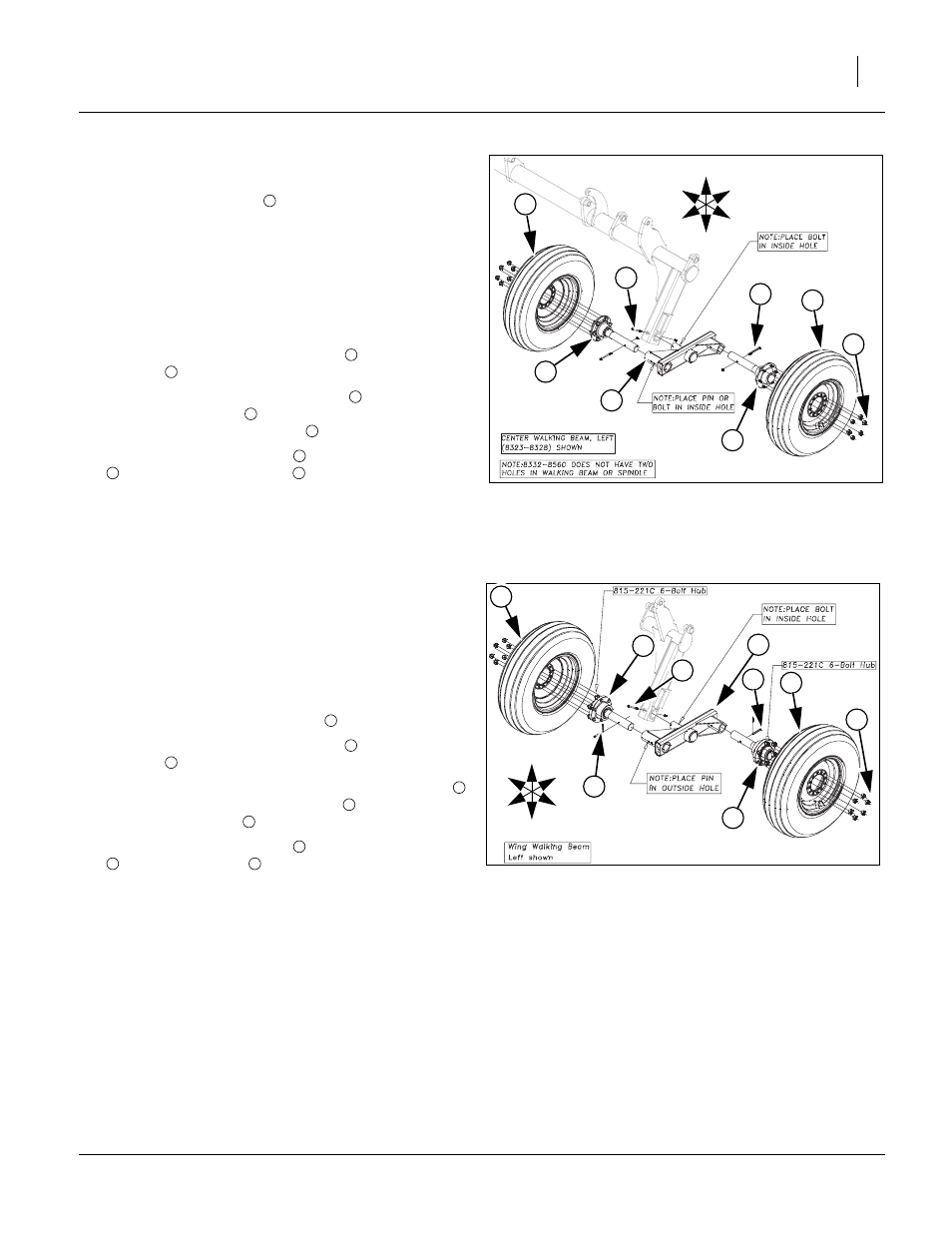
Center Transport
Note: See “Tires Chart” on page 26 for proper tire sizes for
tire/wheel assembly
.
Refer to Figure 15
Note: See transport section of “Parts Manual” for proper
parts breakdown for center walking beam assem-
blies (left hand and right hand) for model of machine
purchased. See notes on drawing for proper hole
placement of walking beam spindle and front tube on
walking beam.
86. Install the walking beam assembly
with correct 5/16
hex bolt
and 5/16 top lock nut.
87. Align hole in spindle/hub assembly
to hole in walk-
ing beam assembly
secure with hex bolt and top
lock nut or pin and cotter pin
.
88. Mount tire/wheel assembly
to spindle/hub assembly
with 9/16 or 5/8 lug nuts
.
Note: Left hand shown is shown. Repeat same procedure
for right side.
89. Tighten all bolts to specs, See “Torque Values Chart”
Wing Transport
Refer to Figure 16
Note: See transport section of “Parts Manual” for proper
parts breakdown for wing walking beam assemblies.
See notes on drawing for proper hole placement on
walking beam spindle and front tube of walking
beam. See “Tires Chart” on page 26 for proper tire
sizes for tire/wheel assembly
.
90. Install the walking beam assembly
with correct 5/16
hex bolt
and 5/16 top lock nut.
91. Align hole in spindle/hub assembly (13.5” spindle)
to hole in walking beam assembly
secure with 5/16
x 2 13/16 pin clevis
and cotter pin.
92. Mount tire/wheel assembly
to spindle/hub assembly
with 9/16 lug nuts
.
Note: Left hand shown is shown. Repeat same procedure
for right side.
93. Tighten all bolts to specs, See “Torque Values Chart”
Figure 15
Center Transport
41891
3
U
D
F
B
L
R
2
6
4
1
3
5
5
5
1
2
3
1
4
5
3
6
Figure 16
Wing Transport
42732
3
U
D
F
B
L
R
2
6
4
1
3
5
5
4
5
1
2
3
1
4
5
3
6