Caution – Great Plains 4000TT Operator Manual User Manual
Page 71
Great Plains Mfg., Inc.
Section 5: Operating and Maintenance
12/15/2004
Series I 1000TT - 4000TT Turbo-Till 586-043M
69
11. Check for any bolts that may need tightened
or retightened. Grease all the hinge points.
The hubs come pre-greased and will not need
more grease at this time.
12. Put lift cylinder transport locks in place and
refold the machine slowly. Put wing stop pins
in place. Always use the transport locks and
pins when moving from field to field. You are
now ready to go to the field.
13. See Section 2: Hydraulics for setting hydraulic
down pressure control valves.
General Operating Instructions and In-Field Adjustments
1. Remove the transport locks and pins and
unfold the machine.
2. Set the hydraulic down pressure using the
instructions provided on pages 44 & 45
Caution: Never leave tractor valve
centered when unfolded with machine
in motion
. Machine damage may occur when
wings flex. The hydraulic down pressure
cylinders have no wing flex capability and oil
flow is required when the wings flex up or
down. You must have the tractor fold hydraulic
lever in continuous downward flow or “float”
position before the wings can flex over terrain
in the raised or lowered lift position.
3. If possible have someone observe the machine
during first time operation for levelness—front
to rear and wings to center frame. Adjust each
as needed. For front to rear, either extend or
shorten the length of the turnbuckle on the self-
leveling system. Never run the machine with
the back lower (deeper) than the front. To
adjust the machine from side to side, use the
lift turnbuckle on each wing
4. For best results, if at all possible, run the
machine at a slight angle to the rows. This will
improve trash flow and help spread the residue
more evenly throughout the field.
5. When you have the machine set to the desired
working depth, set the depth stop on the depth
control bar. This is located at the front of the
machine. This will maintain a constant depth
each time after raising and lowering the
machine. Slight tire to ground pressure
should be maintained to prevent cylinder
pin and clevis wear.
6. If after setting the depth stop, the detent on the
tractor kicks out before the stop contacts the
button on the depth stop, slow the hydraulic
flow speed down. If this problem still persists,
contact the factory service representative for
other possible adjustments.
7. Adjust the drag to leave the desired results
while maintaining the trash flow through the
drag.
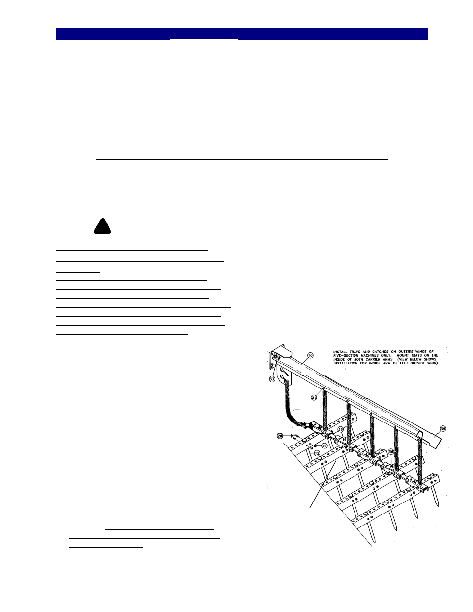
a.) On the spike drag, start with 5 links
hanging from the chain in drag arm bottom
slot. (This is the starting point for worst
conditions.) The cleaner the ground, the
shorter the pull chain may be pulled up.
On the spike drag, one of the links in the
first row of angles is turned over. This
ASSEMBLE WITH LINK UP AS
SHOWN. IN SOME
CONDITIONS THE FRONT
LINK MAY BE ASSEMBLED
DOWN TO HELP START
TRASH TO FLOW THROUGH
THE HARROW.
8/30/2005
!
CAUTION