Hydraulic valve mounting assembly – Great Plains 4000TT Operator Manual User Manual
Page 24
Section 1: Assembly
Great Plains Mfg., Inc.
Series I 1000TT- 4000TT Turbo-Till 586-043M
12/15/2004
22
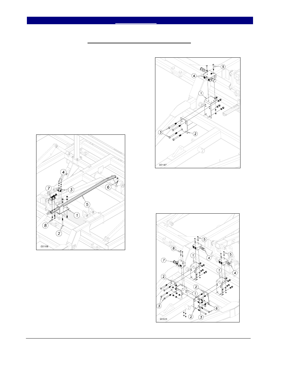
Hydraulic Valve Mounting Assembly
Install the depth stop mounting bracket
(1), Figure 9, to the center frame using one 5/8
x 4 x 6½ u-bolt (2), lock washers and hex nuts.
Bolt the depth stop valve (3) on top of the
bracket using the 5/16 x 2” hex bolts (4) along
with lock washers. Insert the depth stop tube
(5) into the mounting bracket (1) and attach to
the level bar with ½ flat washer and 5/32 x 1½
cotter pin (6). Bolt the depth stop assembly (7)
onto the depth stop tube (1) with two ½ x 2½
hex bolts (8) securing with lock washers and
hex nuts.
Figure 9
For 17’, 22’ and 30’ machines, attach
the valve mounting bracket (1) and backing
plate (2) to the hitch frame as shown in Figure
10. Use four ½ x 4½ hex bolts (3) with hex
nuts and lock washers. Attach the bypass/
pressure reducing valve (4) with 5/16 x 3 hex
bolts (5), hex nuts and lock washers.
For 40’ machine, add second and third
bracket as shown in Figure 11. Use four ½ x 5
½ hex bolts (6) with hex nuts and lock washers.
Figure 10
Bolt the pressure reducing valves (4) to
the brackets with ¼ x 2½ hex bolts (5) Attach
the bypass valve (7) with 5/16 x 3 hex bolts (8),
hex nuts and lock washers.
Figure 11
3/21/2005