Section 1: assembly, Center frame, torque tube & gang bar assembly, Section 1 assembly – Great Plains 4000TT Operator Manual User Manual
Page 16: Assembly
Section 1: Assembly
Great Plains Mfg., Inc.
Series I 1000TT- 4000TT Turbo-Till 586-043M
12/15/2004
14
Assembly
This section covers the proper assembly of the implement. The reference numbers on the
figures give you an indication of the order of assembly. For a complete breakdown of any part not
shown in this assembly section, refer to the parts manual for proper location. Refer to the Appendix
for proper bolt torque values.
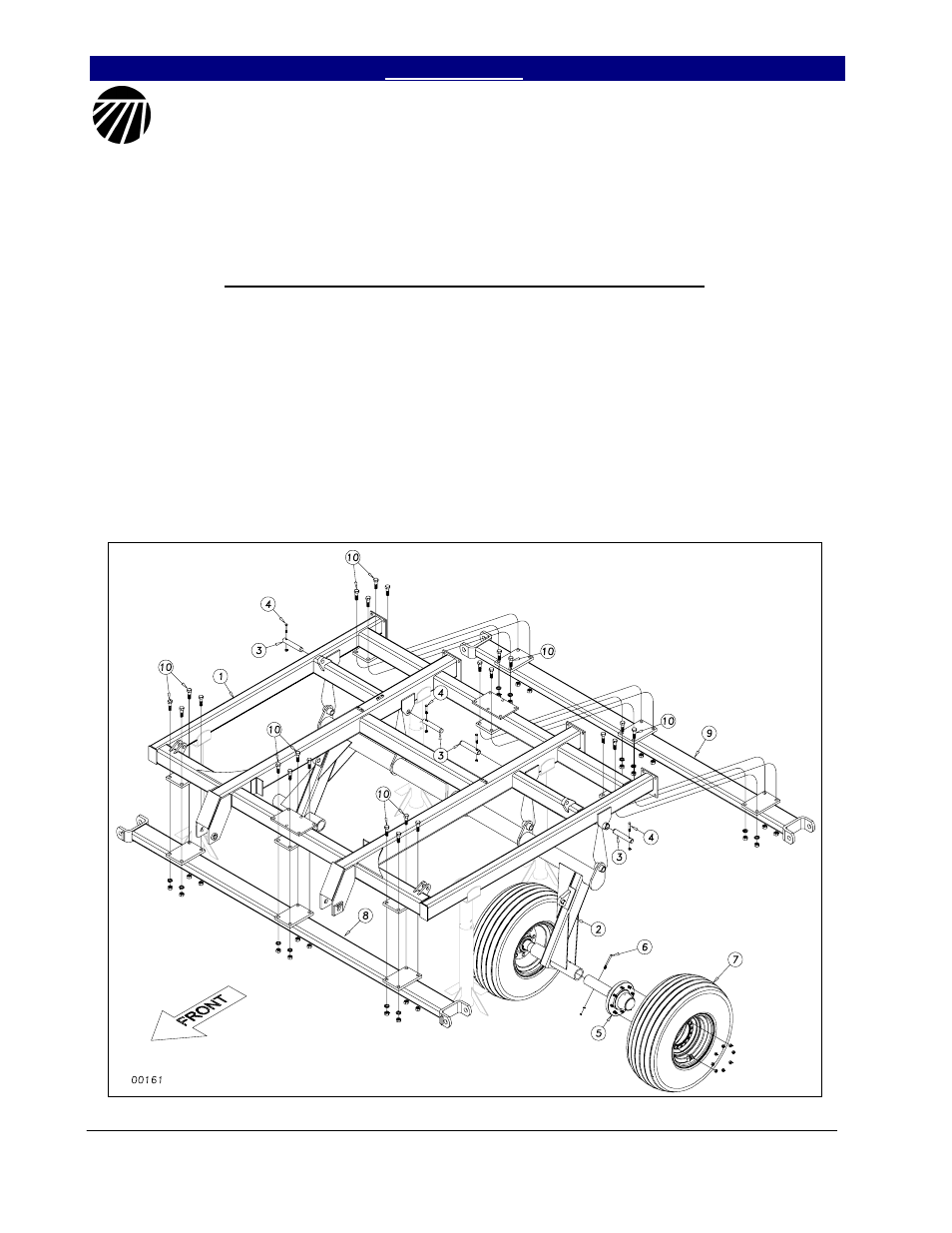
Center Frame, Torque Tube & Gang Bar Assembly
After uncrating the machine, place the
center frame (1) Figure 1, in the center of your
work area on stands. Pin the torque tube (2) to
the center frame with the 1¼ x 7 pins (3) and
secure them with the 3/8 x 2½ hex bolts (4) and
lock nuts.
Slide the hub & spindle assemblies (5)
into the sleeves at the end of the torque tube
wheel arms (refer to Section 3 for proper size
for your model). Use some form of anti-seize
on the spindle before you insert it. Line up the
hole in the spindle with the hole in the sleeve
and secure with 5/16 or ¾ hex bolt (6) with
lock washer and hex nut. Attach the proper tire
and wheel assembly (7) for your model as per
Section 3.
Bolt the front and rear gang bars (8) &
(9) to the center frame using ¾ x 2½ hex bolts
(10), hex nuts and lock washers. Note: the
heavier, weighted gang bar goes on the front.
Figure 1
3/21/2005