Wing and wheel arm assembly – Great Plains 4000TT Operator Manual User Manual
Page 19
Great Plains Mfg., Inc.
Section 1: Assembly
12/15/2004
Series I 1000TT- 4000TT Turbo-Till 586-043M
17
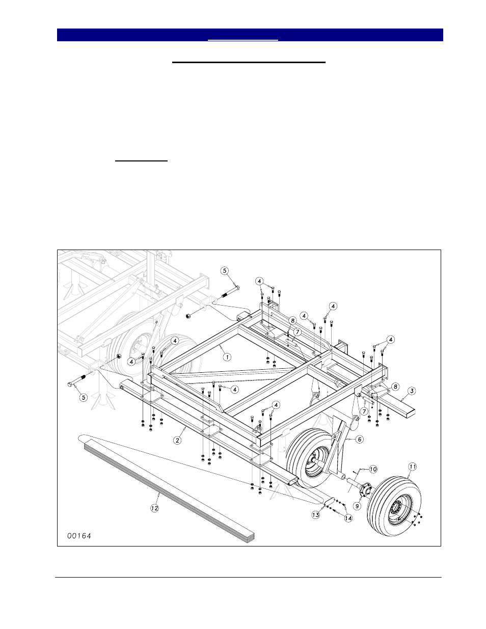
Wing and Wheel Arm Assembly
Place the wing frames (1) Figure 4, on
stands next to the center frame. Bolt the front
and rear gang bars (2) & (3) to the wing frame
using ¾ x 2½ hex bolts (4), nuts and lock
washers. Bolt the wing and gang bar assembly
to the center frame with two 1¼ x 10 Gr. 5 hex
bolts (5) with top lock nuts. Draw the nuts
down tight but do not torque.
Once the wings are attached, insert the
wheel arm bracket (6) into the wing frame
hangers and secure it with 1¼ x 7 pins (7).
Secure the 1¼ x 7 pins with 3/8 x 2½ hex bolts
(8), hex nuts and lock washers.
Slide the wing hub & spindle
assemblies (9) into the sleeves at the end of the
wheel arms (refer to Section 3 for proper size
for your model). Use some form of anti-seize
on the spindle before you insert it. Line up the
hole in the spindle with the hole in the sleeve
and secure with pin or bolt (10) as shown in
Section 3. Attach the wing tire and wheel
assembly (11) to the hubs using bolts or lug
nuts, (see Section 3).
With some heavy attachments, insert
the wing weight ballast flats (12) into the front
wing gang bar (2). Bolt the end caps (13) to the
front gang bar (2) with two ½ x 1 hex bolts (14)
using flat washers and lock washers.
Figure 4
3/21/2005