Center wing stop, fold brackets & lift assembly – Great Plains 4000TT Operator Manual User Manual
Page 17
Great Plains Mfg., Inc.
Section 1: Assembly
12/15/2004
Series I 1000TT- 4000TT Turbo-Till 586-043M
15
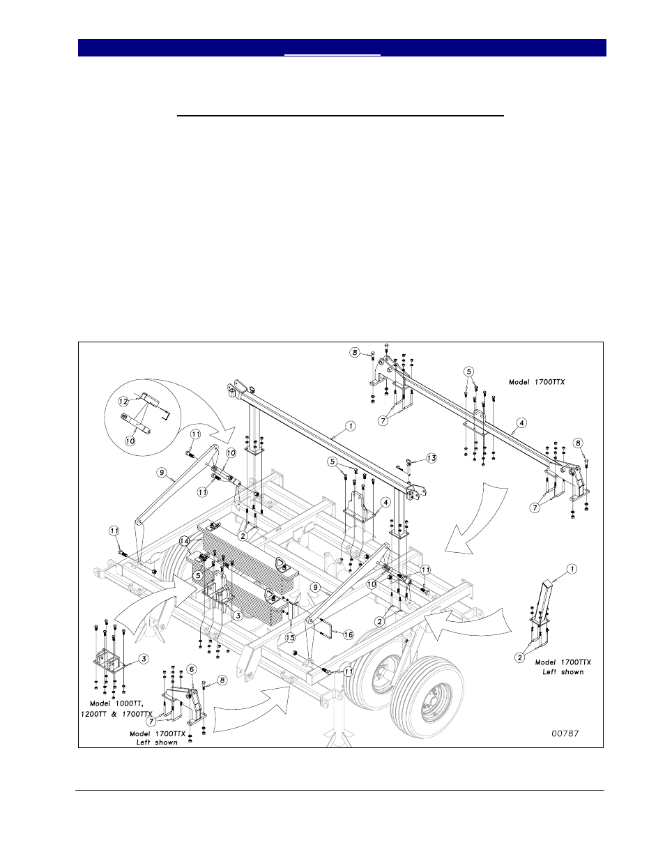
Center Wing Stop, Fold Brackets & Lift Assembly
On folding models, attach the center
wing stop (1) Figure 2, to the center frame
with 5/8 x 3 x 6½ u-bolts (2), using hex nuts
and lock washers (See Machine Layout for
proper placement). Bolt the front wing fold
bracket (3), and rear fold bracket (4), if
applicable, to the center frame using 5/8 x 2
GR 8 hex bolts (5), hex nuts and lock
washers. On 1700TTX* also assemble Inside
Hinges (6) to front bar using 5/8 x 4 x 6½ u-
bolts (7) and ¾ x 3½ hex bolts (8) with lock
washers and hex nuts.
Bolt the cylinder mount bars (9) and
lift mechanism link (10) to the center frame
using 1 x 3 hex bolts (11) and secure with 1”
lock nuts. Install transport locks (12) to the
lift mechanism links (10) with a 5/16 x 3
quick pin. Install the ¾ x 5¼ usable pin &
retainer (13) in the holders for the wing fold
locks.
If you have the optional center weight
package, insert the weight pairs (14) onto the
center frame. Secure them with weight box
stops (15) and ½ x 6 x 5¼ u-bolts (16), hex
nuts and lock washers.
Figure 2
1/25/2008
* Model 1700TTX is 5 meter foreign export model, not sold in USA.