Hose routing hitch, Gauge wheel (optional), Hose routing hitch gauge wheel (optional) – Great Plains 4000TM Assembly Manual User Manual
Page 44
40
3500-4000TM
Great Plains Manufacturing, Inc.
586-537Q-ENG
12/03/2013
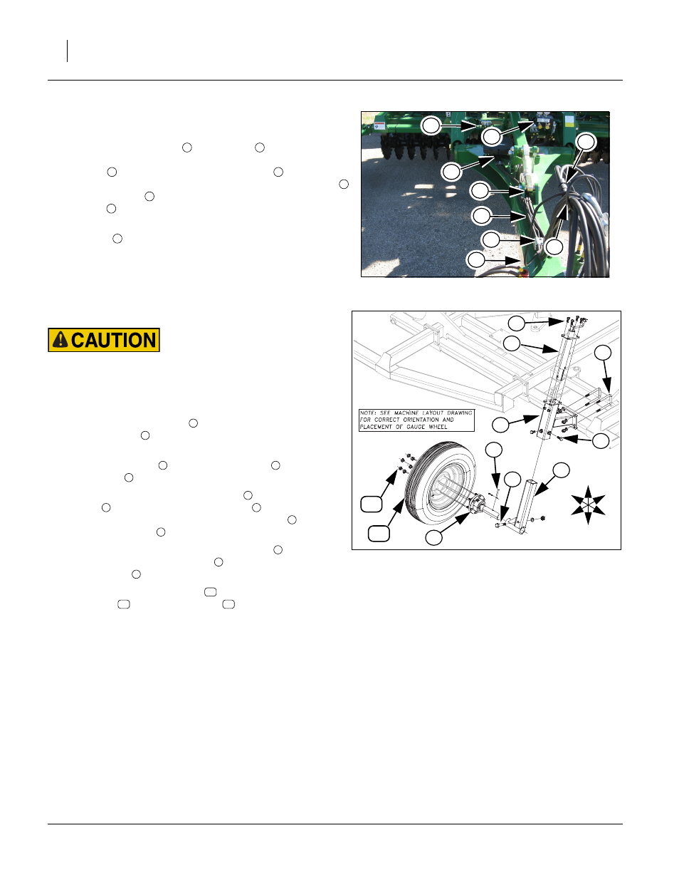
Hose Routing Hitch
Refer to Figure 31
128.Route hydraulic hoses
from valves
, on center brace
bar, gang hoses and light harness, under manual pak
bracket
, under front of hitch turnbuckle
along all
hose clamp blocks and through spring hose holder loop
to front of hitch
as shown. Secure hoses with hose
clamps
, 5/16 hex bolts and 5/16 lock washers.
Note: Be sure all hose clamp bolts are tight. Attach hose
wraps
as needed. Check that all hoses on machine
are fastened properly and they won’t get pinched at
hinge points or drag on ground. Check all connections
again for leaks.
Gauge Wheel (optional)
Refer to Figure 32
Lower machine until coulters are on ground and pressure is off lev-
eling system.
Note: Up to 2 sets of weights (4 weights) may be installed in
positions shown
129.Install wheel arm mount
to wing frame with 5/8 x 3 1/32
x 6 1/2 u-bolts
, secure with 5/8 lock washers and 5/8
nuts.
130.Attach screw jack
to wheel arm mount
with 1/2 x 1 1/
4 hex bolts
, 1/2 top lock nuts.
131.Slide gauge wheel spindle reciever
into wheel arm
mount
, secure with 3/4 x 4 hex bolt
, 3/4 lock washers
and 3/4 nuts. Install the 5/8 x 1 1/4 hex bolts
to the
wheel arm mount
.
132.Align hole in 6-bolt hub/spindle assembly
with hole in
gauge wheel spindle reciever
, secure with 5/16 x 2 13/
16 clevis pin
and 1/8 x 1 cotter pin.
133.Attach wheel/tire assembly
to 6-bolt hub/spindle
assembly
with 9/16 lug nuts
.
134.Tighten all bolts with lock nuts snug, but do not torque.
The rest of the bolts may be tightened to specs, See
“Torque Values Chart” on page 46.
Figure 31
Hose Routing Hitch
42945
5
7
2
4
3
2
1
6
8
1
2
3
4
5
6
7
8
2
6
U
D
F
B
L
R
4
Figure 32
Gauge Wheel
43153
5
10
3
7
1
9
8
11
1
2
3
1
4
5
1
6
7
1
8
5
9
10
11
12