Valve brackets & valves, Valve brackets & hoses, Valve brackets & valves valve brackets & hoses – Great Plains 4000TM Assembly Manual User Manual
Page 15
Great Plains Manufacturing, Inc.
Assembly
11
12/03/2013
586-537Q-ENG
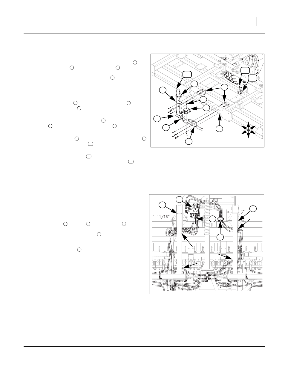
Valve Brackets & Valves
20. Attach bypass and counterbalance valve bracket
and
lock valve bracket
to center brace bar
in proper
locations, shown, See “Valve Brackets & Hoses” below,
with the same 1/2 x 3 1/32 x 6 u-bolts
, 1/2 lock wash-
ers and 1/2 nuts.
21. Be sure hoses are routed as shown in, See “Valve Brack-
ets & Hoses” below.
22. Install bypass valve
on top of valve bracket
with 5/
16 x 3 Gr. 5 hex bolts
, 5/16 lock washers and 5/16
nuts.
23. Fasten the counter balance valve
to side of valve
bracket
with 5/16 x 4 Gr. 5 hex bolts
, 5/16 lock
washers and 5/16 nuts.
24. Install the lock valve
to the top of the valve bracket
with 1/4 x 2 Gr. 5 hex bolts
, 1/4 lock washers and 1/4
nuts.
25. Attach depth control valve
to top of depth stop bracket
(plunger forward), with 5/16 x 2 Gr. 5 hex bolts
and 5/
16 lock washers.
26. Bolts may be tightened to specs, See “Torque Values
Valve Brackets & Hoses
Note: See hydraulic layout drawings in Appendix for complete
routing of hoses. See hydraulic section in “Parts Manu-
al” for complete fitting and hose part descriptions. The
hose lengths will be marked on end of hoses. The wing
fold two way
, bypass
and lock valve
will need
mounted in proper location as shown and hoses routed
correctly before front trusses
and hitch See “Hitch”
on page 13, are installed so front weight kits may be in-
stalled or removed without taking hoses or valves loose.
Install front trusses
, See “Front Trusses & Level
Bar” on page 12, on top of hoses as shown. Set plates
in locations shown before tightening bolts. See “Valve
Brackets & Valves” above, for proper mounting instruc-
tions.
2
1
5
U
D
F
B
L
R
7
4
6
Figure 8
Valve Brackets & Valves
42868
8
9
12
11
3
10
1
2
3
4
5
1
6
7
1
8
9
2
10
11
12
1
2
3
Figure 9
Valve Brackets & Hoses
43867
4
4
1
2
3
4
4