Assembly, Center frame & lift assembly – Great Plains 4000TM Assembly Manual User Manual
Page 12
586-537Q-ENG
12/03/2013
8
3500-4000TM
Great Plains Manufacturing, Inc.
Assembly
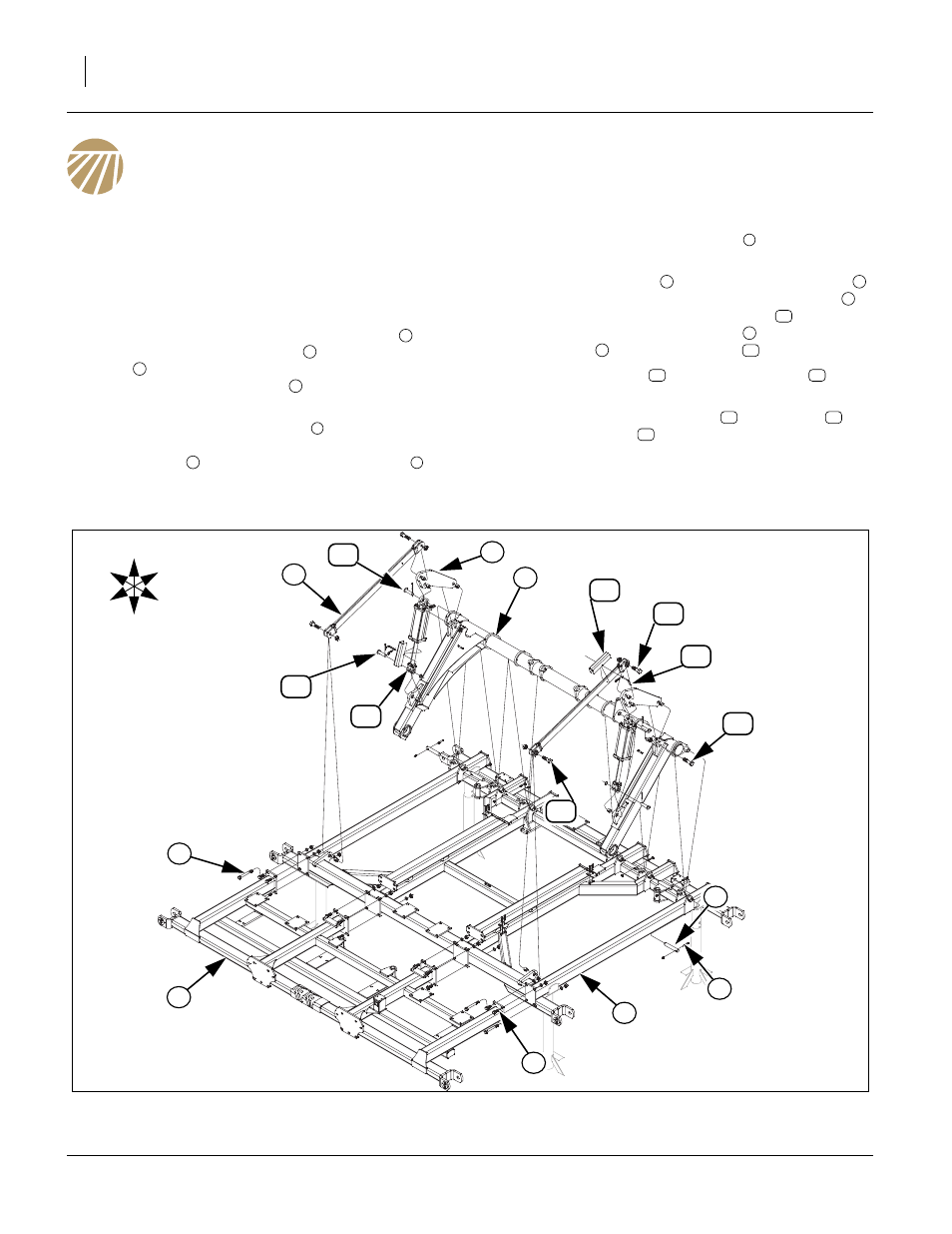
Center Frame & Lift Assembly
Refer to Figure 5
Note: Once the center frame has been uncrated and put
on stands, the brace bar may be installed. See
“Parts Manual” for part numbers and description of
parts.
3.
Align holes in plates of the center brace bar
with
holes on front of center frame
, with 3/4 x 2 hex
bolts
(2 center plates and top holes of outside
plates and 3/4 x 7 hex bolts
(outside plates, bot-
tom holes), secure 3/4 lock washers and 3/4 nuts.
4.
Carefully lower the torque tube
with an overhead
hoist until holes are aligned with the holes on top of
center frame
and secure with 1 1/4 x 7 pins
, 3/8
x 2 1/4 Gr. 8, special thread bolts
and 3/8 top lock
nuts.
5.
Align hole in lift strap
and cylinder mount plate
in proper orientation as shown. Secure lift strap
with 1 x 3 1/4 special thread hex bolts
and 1 lock
nuts, rear of cylinder mount plate
to plates of
torque tube
with 1 x 4 hex bolt
and 1 lock nut.
6.
Install the cylinders
using 1 x 3 1/8 pins
, 1.5 x
1.0 x.075 machine washers and 3/16 x 2 cotter pin.
7.
Install cylinder transport locks
to cylinders
using 3/8 x 3 pins
and clip pins
8.
Tighten all bolts with lock nuts snug, but do not
torque. The rest of the bolts may be tightened to
specs, See “Torque Values Chart” on page 46.
1
2
3
4
5
2
6
7
8
9
8
10
9
5
11
12
13
14
12
15
Figure 5
Center Frame & Lift Assembly
43127
11
12
6
U
D
F
B
L
R
2
4
1
5
13
15
7
9
8
10
10
13
14
3