Inside wing & lift assembly – Great Plains 4000TM Assembly Manual User Manual
Page 18
14
3500-4000TM
Great Plains Manufacturing, Inc.
586-537Q-ENG
12/03/2013
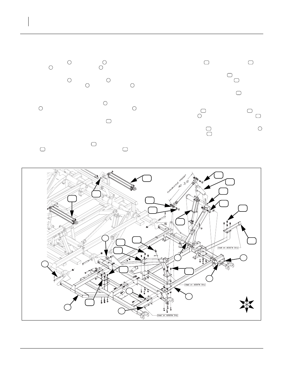
Inside Wing & Lift Assembly
Refer to Figure 12
43. Attach wing brace
to wing frame
with 3/4 x 2
hex bolts
and 3/4 x 7 hex bolts
(Model 4000
only), secure 3/4 lock washers and 3/4 nuts.
44. Attach wing brace
and wing frame
to center
frame with wing hinge pins
, 1 1/4 flat washers
(rear side of wing hinge tubes only, do not use
washer on wing brace bar) and 1 lock nuts.
45. Install LH and RH wing wheel arms
with 1 1/4 x 7
pins
, 3/8 x 2 1/4, Gr. 8, special thread hex bolts
and 3/8 top lock nut.
Note: Be sure wing turnbuckle assembly
is preset at
40 3/8” before installing as shown below. See
gang angle adjustment in “Operator Manual”
before going to field.
46. Install wing wheel turnbuckles
and cylinder mount
plate
in position shown with 1 x 4 hex bolts
and
1 lock nuts.
47. Install wing lift cylinders
with 1 x 3 1/8 pins
, 1.5
x 1.0 x.075 machine washers and 3/16 x 2 cotter pin.
48. Now the base end of fold cylinders
may be
hooked up with the 1 x 3 1/8 clevis pin
, 1.5 x 1.00
x 0.075 machine washer and 3/16 x 2 cotter pin.
49. Do not hook up rod end of fold cylinder
until sys-
tem is purged of air. See “Purging Hydraulic Sys-
tem” on page 28.
50. Attach front wing stop
and rear wing stop
to
plates of wing frame
with 5/8 x 1 1/2 hex bolts
,
5/8 lock washers and 5/8 nuts.
51. Attach wing stop bracket
to plate of wing frame
with 5/8 x 1 1/2 hex bolts
, 5/8 lock washers and 5/
8 nuts.
52. Tighten all bolts with lock nuts snug, but do not
torque. The rest of the bolts may be tightened to
specs, See “Torque Values Chart” on page 46.
1
2
3
4
1
2
5
6
7
8
9
10
10
11
12
13
14
15
14
15
16
17
2
18
20
2
18
U
D
F
B
L
R
6
4
Figure 12
Inside Wing & Lift Assembly
43141
3
1
5
8
12
2
7
11
10
12
13
19
16
15
15
14
18
9
18
17
12
14
18
18
20