Depth stop & angle gauge – Great Plains 4000TM Assembly Manual User Manual
Page 22
18
3500-4000TM
Great Plains Manufacturing, Inc.
586-537Q-ENG
12/03/2013
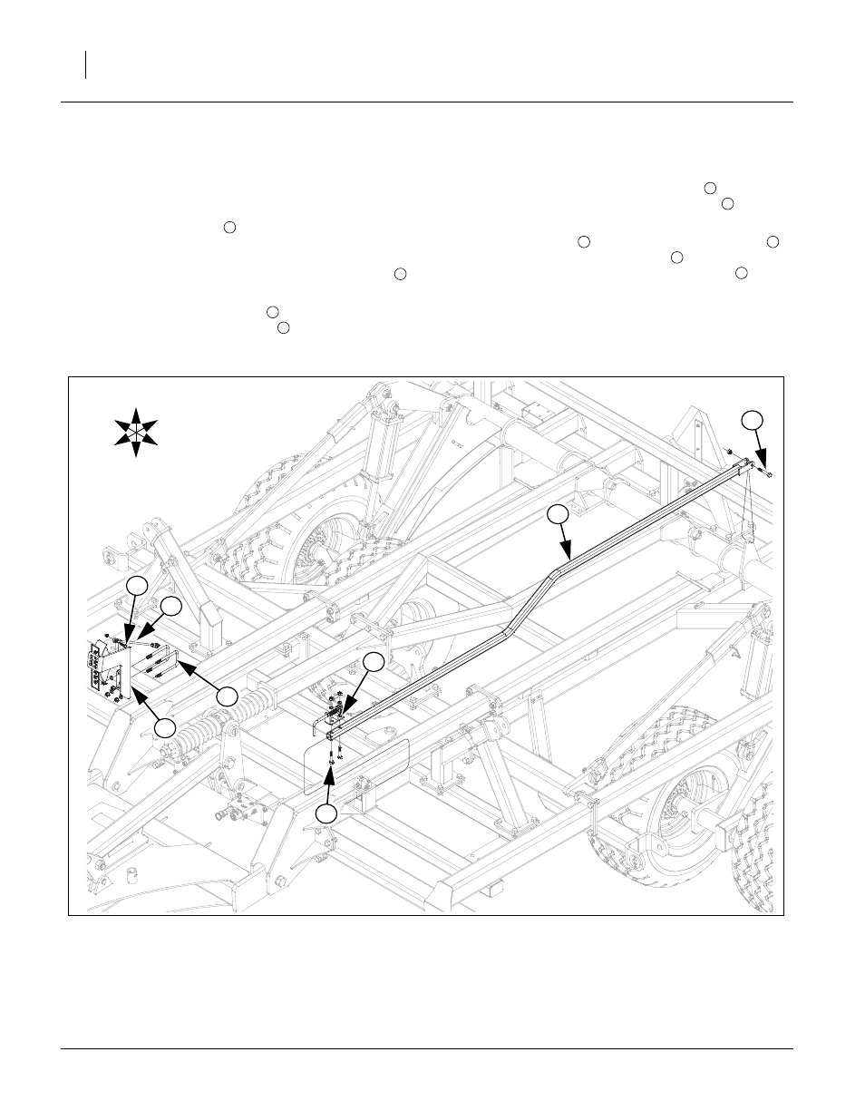
Depth Stop & Angle Gauge
Refer to Figure 16
Note: See machine layout drawings in Appendix for
proper gang gauge placement for each model.
68. Slide depth stop tube
from rear of machine under
left wing stop through square hole on depth control
bracket on center wing brace. Align rear holes over
lever on torque tube, secure with 1/2 x 3 hex bolt
,
1/2 top lock nut.
69. Fasten depth stop assembly
on top of depth stop
tube with 1/2 x 2 1/2 hex bolts
, 1/2 lock washers
and 1/2 nuts.
70. Attach angle gauge bracket assembly
to front of
center frame with 1/2 x 3 1/32 x 5 u-bolts
, 1/2 lock
washers and 1/2 nuts.
71. Attach gauge link
to gauge bracket assembly
,
secure with 3/8 x 1 1/4 hex bolts
and 3/8 top lock
nuts. Do not attach other end of gauge link
until
gang assemblies are installed.
72. Tighten all bolts with lock nuts snug, but do not
torque. The rest of the bolts may be tightened to
specs, See “Torque Values Chart” on page 46.
1
2
3
4
5
6
7
5
8
7
Figure 16
Depth Stop & Angle Gauge
43145
U
D
F
B
L
R
8
5
6
4
3
1
2
7