Marker setup (option), Shaft monitor (option), Marker setup (option) shaft monitor (option) – Great Plains 3N-4020 Operator Manual User Manual
Page 22
18
3N-4010F/3N-4010HDF/3N-4020F
Great Plains Manufacturing, Inc.
196-359M
2013-10-29
Marker Setup (Option)
If markers are not installed, install them now per the
instructions included with the markers.
Once installed, verify that they have been correctly bled
(See “Bleeding Markers” on page 107).
Set initial marker extension - the distance to the mark on
each side from the outside row unit on that side.
1.
Move the hitched drill to a typical flat field.
2.
Extend a marker on one side (see page 33). Pull for-
ward a few feet or a meter or so to leave a mark.
3.
Measure from the centerline of the outside row unit
(whether that row unit is to be used or not) to the
mark, along a line parallel to the wing.
Refer to Figure 175 through Figure 180 on pages 127 and 129
4.
Check the measurement against the value recom-
mended by Great Plains.
Refer to Figure 12
If the marker extensions need adjustment:
5.
Loosen the nuts
securing the U-bolt
at the
outer marker section.
6.
Slide the inner tube
in or out, and re-secure nuts.
See page 69 for further marker adjustments. Re-check
marker extension when changing disk angle, or when
inverting the disk, as both adjustments change the posi-
tion of the centerline of the mark.
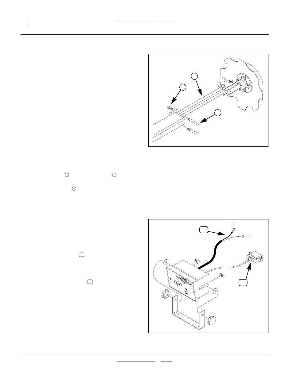
Shaft Monitor (Option)
1.
Choose a tractor cab location where the module
does not obstruct vision, and the shaft indicators can
be easily seen if an alert sounds.
Refer to Figure 13
2.
Route the power leads
to a source of +12 Vdc
power.
Color code is red+, black-.
3.
Use a tie to secure the power lead.
4.
Route the monitor harness
to the tractor hitch.
Use ties to secure the hitch lead.
For operation, see:
“Shaft Monitor Operation (Option)” on page 33.
For ordering information, see:
“Shaft Monitor” on page 121.
Figure 12
Adjusting Marker Extension
18878
1
2
3
1
2
3
Figure 13: 823-060C
Shaft Monitor
28241
P
H
P
H