Dual-marker/sequence valve speed, Marker shear bolt replacement – Great Plains 3N-4020 Operator Manual User Manual
Page 112
108
3N-4010F/3N-4010HDF/3N-4020F
Great Plains Manufacturing, Inc.
196-359M
2013-10-29
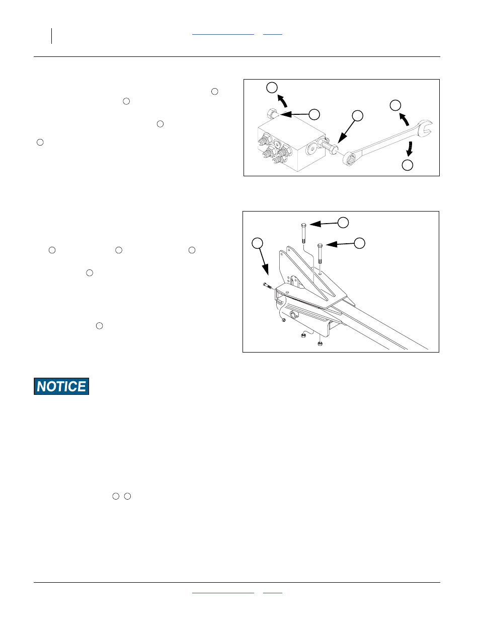
Dual-Marker/Sequence Valve Speed
There is one adjustment screw for unfolding speed
and one for folding speed
. You can identify adjustment
screws by markings stamped in valve body.
Turn adjustment screws clockwise (
: slower) to
decrease [un]folding speed and counterclockwise
(
: faster) to increase [un]folding speed.
With tractor idling at a normal operating speed, adjust
marker folding to a safe speed. Excessive [un]folding
speed could damage markers and void the warranty.
After adjusting the folding speed, tighten jam nuts on hex
adjustment screws to hold settings.
Marker Shear Bolt Replacement
Refer to Figure 151
The marker arm is attached to marker body with a pivot
bolt
and a shear bolt
. A third clamp bolt
acts as a
hold-down for the top of the marker shear base.
The shear bolt
is designed to fail if the marker tip gets
hung up on an obstacle. This prevents damage to the
marker.
If the shear bolt fails, replace it with a bolt of identical
size and grade, or one of similar strength.
The supplied bolt
is Great Plains part:
802-589C HHCS 7/16-14X2 GR5
This is a
7
⁄
16
-14 x 2in Grade 5 bolt. If an exact replace-
ment is not immediately available, temporarily substitute
a metric bolt, M10x0.75 Class 8.8.
Machine Damage Risk:
Do not replace the shear bolt with a higher grade bolt, or the
next obstruction may result in marker damage.
Note: Do not replace the shear bolt with a lower grade
bolt, or smaller bolt, or you may experience nui-
sance shears.
If conditions are causing frequent shears, keep spare
bolts in the storage holes of the marker shear base.
Before installing a new shear bolt, tighten the
5
⁄
8
-11x5in
pivot and clamp bolts (
,
) just enough so the marker
shear arm moves with some resistance when pushed by
hand.
Note: Repeat the above bolt adjustment step at the be-
ginning of each season.
1
2
F
S
S
Figure 150
Sequence Valve Adjustment
14048
1
2
S
F
Figure 151
Marker Shear Base
22514
1
2
3
1
2
3
2
2
1
3