Appendix b - initial setup, Installation instructions, Figure callouts – Great Plains 1007NT Operator Manual User Manual
Page 75: Connector identification
10/06/2010
150-290M
Great Plains Manufacturing, Inc.
Appendix B - Initial Setup
71
Appendix B - Initial Setup
Installation Instructions
This sections covers initial setup items, and features,
options and accessories ordered later or not factory-
installed.
Figure Callouts
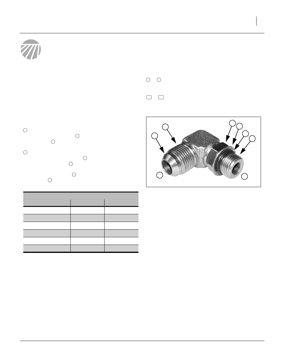
Connector Identification
JIC - Joint Industry Conference (SAE J514)
Note straight threads
and the
37
° cone on “M” fittings (or 37° flare on “F”).
ORB - O-Ring Boss (SAE J514)
Note the straight threads
and,
elastomer O-Ring
.
Fittings needing orientation, such as the ell above,
also have a washer
and
jam nut
(“adjustable thread port stud”)
Page
Installation
to
callouts identify components in the currently
referenced Figure or Figures. These numbers
may be re-used from page to page.
to
callouts reference new parts. The descriptions
match those on the cartons, bags or item tags,
as well the current Parts Manual.
1
9
11
43
Fittings Torque Values
Fitting
Ft-Lbs
N-m
9
⁄
16
JIC
18-20
24-27
9
⁄
16
ORB w/jam nut
12-16
16-22
9
⁄
16
ORB straight
18-24
24-32
3
⁄
4
JIC
27-39
37-53
3
⁄
4
ORB w/jam nut
20-30
27-41
3
⁄
4
ORB straight
27-43
37-58
1
3
2
8
7
6
5
4
Figure 65
Hydraulic Connector ID
25188