Coulter depth (all rows), Initial setup, Fine adjustment – Great Plains 1007NT Operator Manual User Manual
Page 33: Initial setup fine adjustment
Great Plains Manufacturing, Inc.
Adjustments
29
10/06/2010
150-290M
Coulter Depth (All Rows)
Refer to Figure 16
Group coulter depth is controlled by the height at which a
depth control valve
stops retraction of the front (rock-
shaft) cylinders. Further adjustment is available at the
front lift cylinder eyebolt.
Normal practice is to set coulter depth approximately 1 inch
(2.5cm) deeper than desired seed depth.
Note: Do not lower coulters to aid in penetrating hard soil.
Instead, increase coulter down pressure by adding
weight to drill. See “Coulter Down Pressure” on
page 30.
Initial Setup
These instructions assume an initial coulter depth of 2in
(5cm) is desired. Perform this setup hitched to a tractor,
on level ground similar to expected planting conditions;
the coulters need to penetrate to confirm desired depth.
Check that the front eyebolt reveal is at least 2
9
⁄
16
in
(65.3mm), the factory default.
2.
On level ground, fully raise the drill, then lower it until
the coulter blades just touch the ground. Set lift cir-
cuit to neutral to hold that height.
Refer to Figure 16
Note: If the drill stops lowering before reaching the
ground, raise the drill and install lift lock channels.
Use the depth control valve knob
to back the
valve body
away from the stop bolt
. Remove
locks and retry step 2.
3.
Adjust the control valve knob
until there is a
13
⁄
32
in
(1 cm) gap between the tip of the valve actuator
rod
and the head of the stop bolt
.
Fine Adjustment
These instructions presume the Initial Setup above has
been completed, and the drill is hitched to a tractor on
suitable test ground.
4.
Lower drill and pull forward a few feet. Check coulter
depth.
5.
If coulter depth requires adjustment, rotate depth
stop valve knob. Each turn of the knob changes
coulter depth by about
3
⁄
16
in (4.4mm).
Back valve body away from bolt for deeper.
Advance valve toward bolt for shallower.
If desired depth cannot be reached due to the cylinder
being fully retracted, adjust eyebolt (next topic).
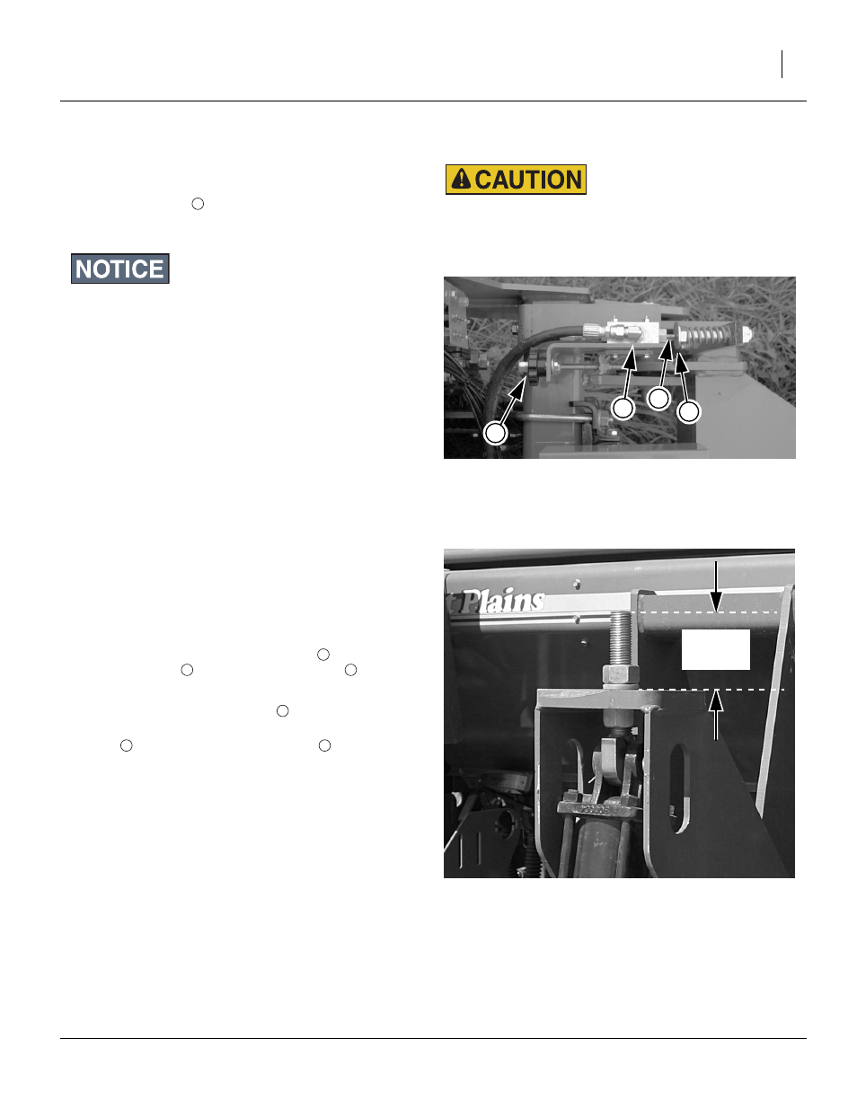
Figure 16
Depth Control Stop Valve
28445
1
2
3
4
Falling Frame Hazard:
Make adjustments with drill lowered, or locked up. Making
adjustments with drill partially raised can result in sudden
downward movement of frame, with risk of serious injury.
Figure 17
Front Eyebolt Factory Setting
28446
2
9
⁄
16
in
(65.3mm)
2
3