Install tower weldments – Great Plains 3N4010HDA Predelivery Manual User Manual
Page 25
Great Plains Manufacturing, Inc.
Air Drill Pre-Delivery
23
10/10/2008
196-444Q
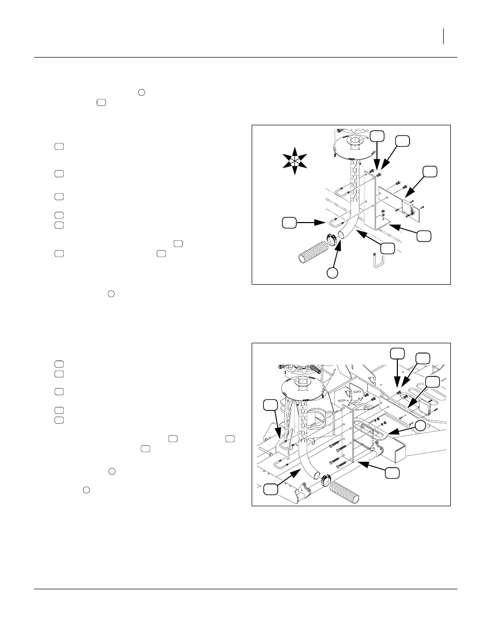
Install Tower Weldments
Start with the outside tower
on the left wing. The mod-
ule mount plate
(if any) may be installed now or at
Refer to Figure 22 and Figure 17 on page 20
66. Select two:
168-216H DISTRIBUTION TOWER WELDMENT
and if the drill was ordered with the optional Block-
age Monitor, select two:
168-465D
DIST TOWER MODULE MOUNT PLATE
67. Select four (4) each:
806-010C U-BOLT 1/2-13 X 2 1/2 X 3 1/2
and eight (8) sets:
804-015C WASHER LOCK SPRING 1/2 PLT
803-020C NUT HEX 1/2-13 PLT
Loosely assemble the weldments
to the mounts
. The module mount plate
is to the rear, side
with smaller holes at top, extending to wing center
(outer tower plate extends to drill center; mid-wing
tower plate extends away from drill center).
68. Orient the inlet
to point in the direction specified in
the “Tower Inlet Angle (Figure 17)” table on
page 20 and Figure 17. Adjust the tower height, from
top of cap to reference point, per the “Tower Height
(Figure 18)” table on page 20. Secure the U-bolts.
Refer to Figure 23 and Figure 17 on page 20
69. Select one each:
168-216H DISTRIBUTION TOWER WELDMENT
168-465D
DIST TOWER MODULE MOUNT PLATE
two each:
806-010C U-BOLT 1/2-13 X 2 1/2 X 3 1/2
and four (4) sets:
804-015C WASHER LOCK SPRING 1/2 PLT
803-020C NUT HEX 1/2-13 PLT
Loosely assemble the weldment
to the mount
.
The module mount plate
is to the center, side with
smaller holes up, extending to drill back.
70. Orient the inlet
to point to the rear. Set the tower
height to 33in (83.8cm) above the top of the reinforc-
ing ring
. Secure the U-bolts.
71. Repeat step 66 through step 70 for the right side of
the drill.
Figure 22
Tower Weldments, Left Wing
27058
82
77
50
39
U
D
F
B
L
R
14
16
i
1
82
14
82
77
50
39
14
16
82
Figure 23
Tower Weldment, Left Center
28182
82
77
50
39
14
23
1
14
82
77
50
39
14
23
82