SARGENT 7800 Knob Locks User Manual
Page 2
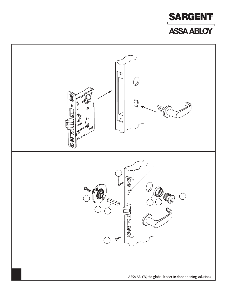
Inside of
door
Outside of
door
G
F
E
D
D
C
A
B
Inside of
door
(4) Slide cylinder (A) through spring (B) &
collar (C) (or escutcheon) and thread
into lock until cylinder face is flush
with collar (C) (or escutcheon edge).
The key slightly pulled out of cylinder
will help to thread the cylinder
Note: SARGENT logo must be
horizontal & on the top portion
of the cylinder
(5) By hand with # 2 Phillips screwdriver,
tighten cylinder clamp screw
(6) Secure lock in door with two
wood screws #12 x 1-1/4" or
machine screws #12-24 x 1/2" (D)
(7) Slide spindle (E) into lockbody hub
(8) Slide adapter & plate assembly (F)
over spindle & secure with two
#8-32 screws (G)
(3) Slide outside lever & rose
assembly (or lever & escutcheon
assembly) through the door and
lock body
(2) Slide lock in door
(1) Important: Check template A7057 to prep door
for function holes, size & location. Verify strike
location according to template. Clean door
pocket and verify hand of lock
RH Door Shown
Outside of
door
Cylinder Clamp
Screw
Note: Keep door open
while installing lock
Note: If installing trim one side,
see separate instruction sheet
R/C & I/C cylinder cores require Control key
(stamped “C”) to install. Must request separately.
If 1 bitted - specify 11311 cut.
2
INSTALLATION INSTRUCTIONS
7800/8200 Series Mortise Locks (Except PT Trim & FE Trim)
See Particular Trim Section for Your Lock
FOR INSTALLATION ASSISTANCE CALL SARGENT AT 1-800-727-5477 • www.sargentlock.com
Copyright © 2009, Sargent Manufacturing Company, an ASSA ABLOY Group company.
All rights reserved. Reproduction in whole or in part without the express written
permission of Sargent Manufacturing Company is prohibited.
A7034G