Default factory setting for 57- shown – SARGENT 59 - Electroguard Delayed Egress User Manual
Page 2
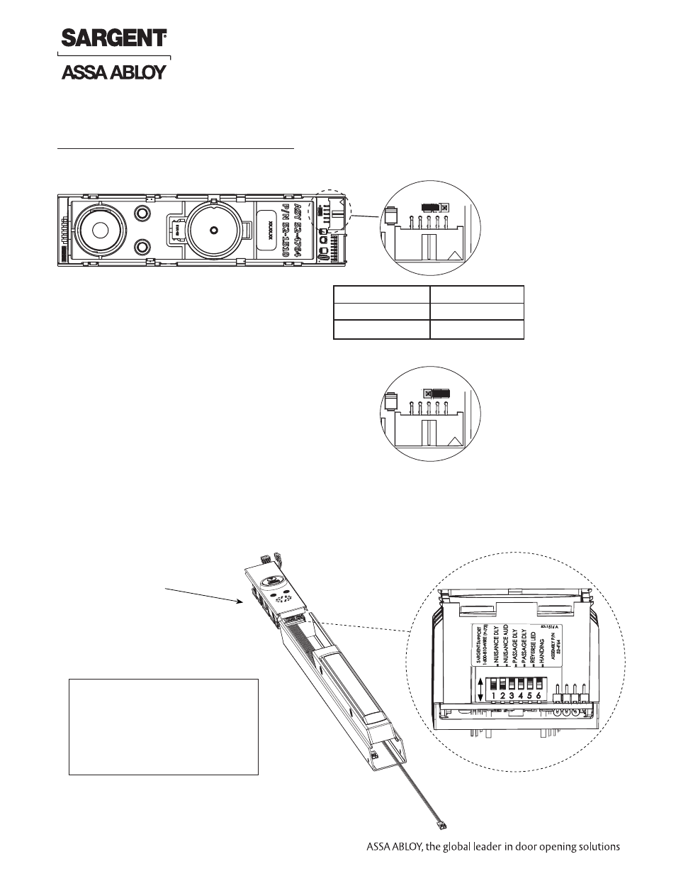
FUNCTION
JUMPER
57-
J5-
1 & J5-2
59-STD
J5-
2 & J5-3
J5
1 2 3
Default factory setting
for 57- shown
NOTES
With Rim, Mortise and Vertical Rod exit devices:
When jumper is missing or in wrong position, the Yellow Diagnostic LED turns ON. To locate (J5) jumper,
remove Insert Assembly and Insert Assembly Plate:
J5
1 2 3
Default factory setting
for 59- shown
Dip Switch Settings
Installer should note DIP switch settings of module being replaced to ensure
same settings are made for replacement module.
OFF
ON
NOTE: Use caution when
removing insert assembly
to avoid damaging the rail
harness connected to the
PCB module assembly.
Insert Assembly
S2
2 1-800-810-WIRE • www.sargentlock.com • A8184A
Copyright © 2013, Sargen
t Manufacturing Company
, an A
SS
A AB
LO
Y G
roup company
. All right
s reser
ved
.
Reproductions in whole or in par
t without express writ
ten permission of Sargen
t Manufacturing Company is prohibited
.
10/31/13
57/59- Prefix 80 Series Exit Device
PCB Module Assembly
Replacement Instructions