SARGENT 59 - Electroguard Delayed Egress User Manual
1replacement instructions, Cylinder orientation
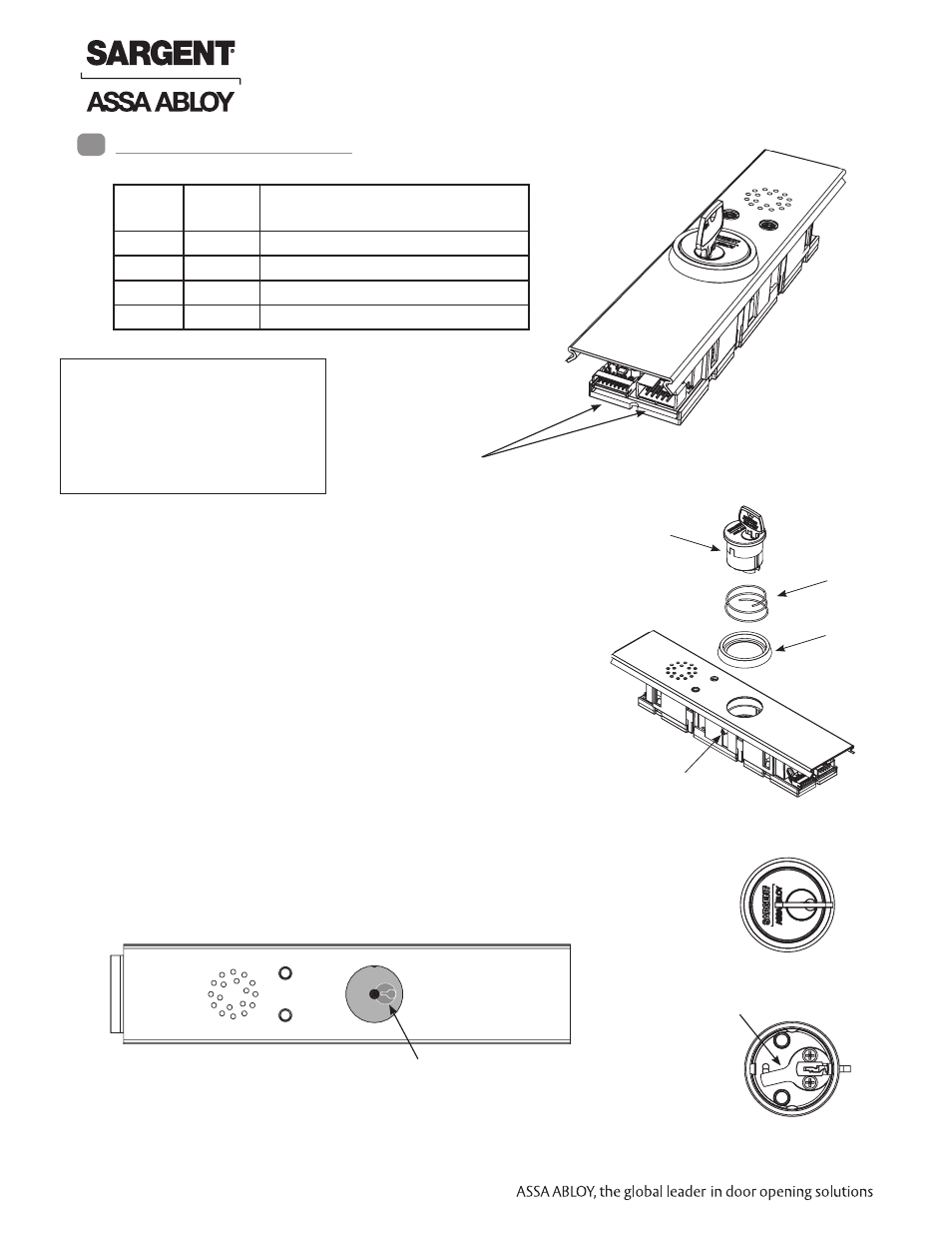
1. Ensure power to device is disconnected.
2. Carefully disconnect all connectors (Fig. 1).
3. Remove insert assembly from rail mounting assembly.
4. Loosen set screw by turning counter-clockwise using
5/64” allen wrench.
5. Extract and slide cylinder through spring and collar.
Cylinder Orientation
Top View with cylinder removed
Set Screw
Collar
Spring
Cylinder with Key
See illustration on circuit board for correct orientation of
cylinder/cam when installing.
Note that proper position of cam allows for removal of key.
Insert Assembly
When replacing cylinder, slide cylinder through spring
then collar, taking care to orient cylinder as shown.
Bottom of Cylinder
Cylinder Cam
Illustration (on circuit board)
1
Replacement Instructions
Top of Cylinder
Prefix
Part
Number
Description
PCB Module Assembly Replacement
59-
52-4837
Standard
59- BC- 52-4838
BOCA (30 seconds)
57-
52-4830
Standard
57- BC- 52-4831
BOCA (30 seconds)
Connector Locations
Fig. 1
NOTE: Use caution when
removing insert assembly
to avoid damaging the rail
harness connected to the
PCB module assembly.
1 1-800-810-WIRE • www.sargentlock.com • A8184A
Copyright © 2013, Sargen
t Manufacturing Company
, an A
SS
A AB
LO
Y G
roup company
. All right
s reser
ved
.
Reproductions in whole or in par
t without express writ
ten permission of Sargen
t Manufacturing Company is prohibited
.
10/31/13
57/59- Prefix 80 Series Exit Device
PCB Module Assembly
Replacement Instructions