SARGENT FM8700 Surface Vertical Rod Exit Device User Manual
Page 5
5
A7827D 3-10-10
Copyright © 2006-2010, Sargent Manufacturing Company, an ASSA ABLOY Group
company. All rights reserved. Reproduction in whole or in part without the express
written permission of Sargent Manufacturing Company is prohibited.
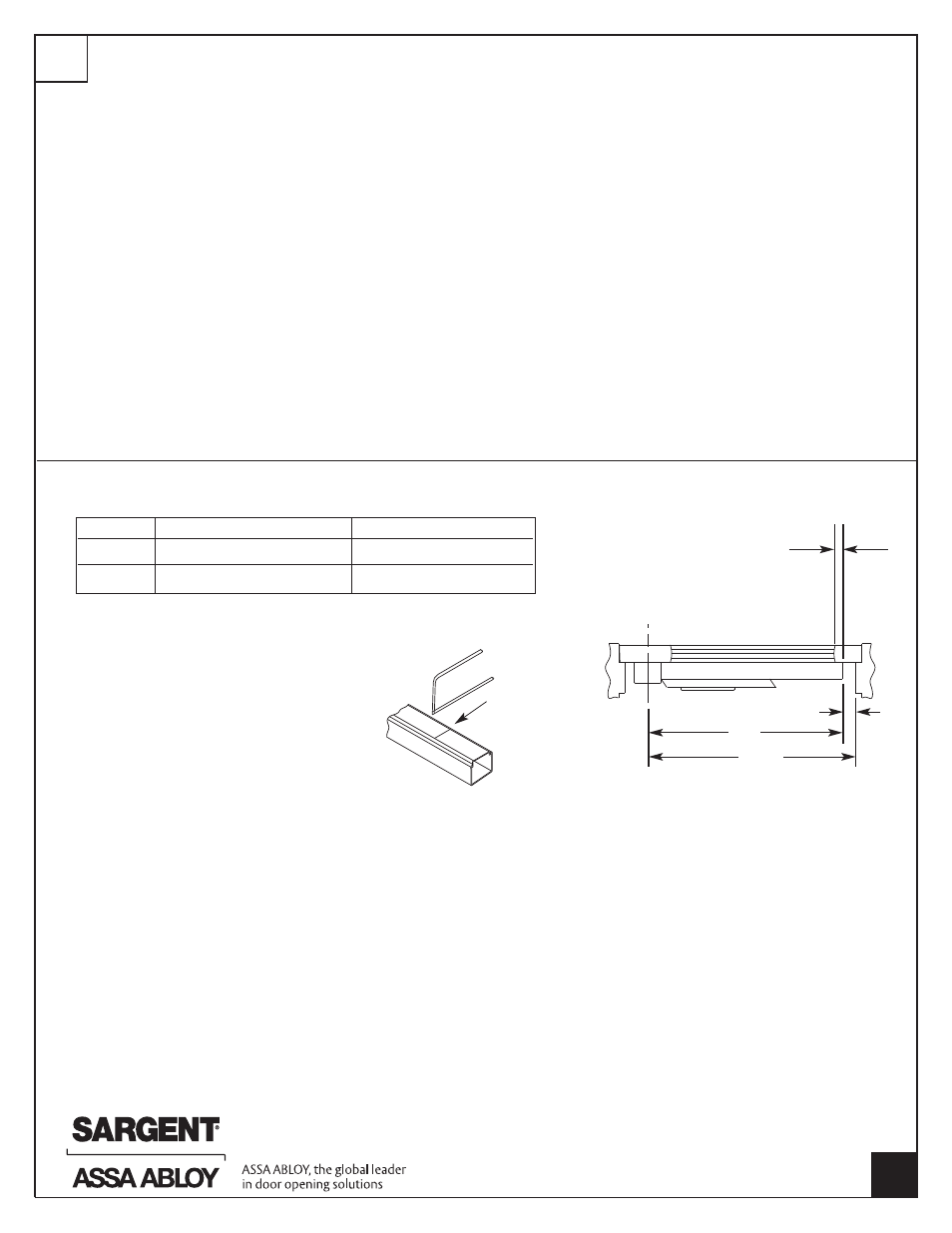
RAIL
MAX DOOR WIDTH
MIN DOOR WIDTH
E
32"
24"
F
36"
33"
ADJUST TOP AND BOTTOM LATCH BOLTS FOR MAXIMUM
ENGAGEMENT
ROUGH adjustments are made by changing the hole used for the
adjustment pin.
FINE ADJUSTMENTS: Turn rod INTO TOP and BOTTOM CASES
to SHORTEN, or OUT of TOP AND BOTTOM CASES to
LENGTHEN.
TOP ROD: Push on the door AND the rail at the same time. As
soon as the door opens, release the rail. The top bolt should be in
the hold back position. If not, extend the top bolt.
NOTE: Top bolt must go into hold back position BEFORE the door
opens.
BOTTOM ROD: Extend the bottom bolt for maximum engagement
with bottom strike.
When the top bolt is in hold back, it also holds the bottom bolt in
the retracted position. When the bottom bolt is retracted, the bolt
must clear the bottom strike by 1/8" minimum through the swing
of the door.
When adjustment is completed, install top and bottom rod guides
at midpoint between center and top and bottom chassis, using (2)
#10-24 x 1-1/4" Ov.Hd.screws per guide.
Install center chassis cover using (4) #8-32 x 5/16" screws.
11
ADJUST TOP & BOTTOM RODS
RAIL LENGTHS AND CUTTING INSTRUCTIONS
TOP VIEW OF EXIT DEVICE
For doors with stile, the rail must
overlap stile by 1/2" or more
Vertical reference line
(CL of chassis)
1-3/4" min.
“X”
“Y”
Cut off mark
Determine rail length dimension “X” by subtracting
1-3/4" from dimension “Y”.
1. Dog push rail and cut off at mark.
2. Cut must be straight.
3. For (43-) flush end cap use cutting
guide provided.
4. Remove sharp edges with file.