Install top case, Securing interlocking shim, Install center chassis – SARGENT FM8700 Surface Vertical Rod Exit Device User Manual
Page 2
2
Copyright © 2006-2010, Sargent Manufacturing Company, an ASSA ABLOY Group
company. All rights reserved. Reproduction in whole or in part without the express
written permission of Sargent Manufacturing Company is prohibited.
A7827D 3-10-10
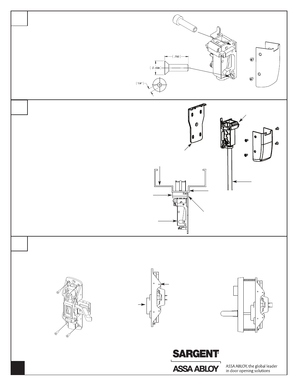
With the door closed center the TOP CHASSIS ASSEMBLY
and INTERLOCKING SHIM on vertical reference line.
Ensure INTERLOCKING SHIM is engaged in TOP
BOLT/STRIKE
Mark location of (4) mounting screws
USE 3/8" DRILL BIT to drill two TOP MOUNTING HOLES
THROUGH DOOR. Install (2) sex nuts, p/n 60-0502 from
OUTSIDE door surface. Install (2)
-12-24 x 3/4 Socket Head Cap Screws from INSIDE.
ATTACH USING (2) 12-24 x 3/4" flat head socket head
screws in two BOTTOM mounting holes (1/8" Allen
wrench).
With the TOP CHASSIS ASSEMBLY and INTERLOCKING SHIM
secured, the 659 TOP BOLT/STRIKE should engage the TOP
CHASSIS ASSEMBLY and INTERLOCKING SHIM when door
is closed.
Trace the outline of the INTERLOCKING SHIM
Remove the TOP CHASSIS ASSEMBLY to expose the center
hole on the INTERLOCKING SHIM. Ensure the INTERLOCKING
SHIM is aligned with the tracing. Mark and tap center hole (1)
12-24 x ¾” flat head socket head screw.
REINSTALL TOP CHASSIS ASSEMBLY.
Check for TOP CHASSIS ASSEMBLY and 659 TOP
BOLT/STRIKE engagement. Tighten all screws.
INSTALL TOP CASE COVER using (4) 8-32 x 5/16” screws
3
INSTALL TOP CASE
4
SECURING INTERLOCKING SHIM
SECURE CHASSIS and CHASSIS SHIM with
(4) #10-24 x 3/4" PH.FL.HD.Mach. Screws, 4
corner mounting holes.
NOTE: USE ALL FOUR SCREWS PROVIDED.
POSITION TRIM ON
DOOR - Align spindle
with BELL HOUSING
THRU-BOLT CHASSIS
to ET TRIM with
(2) 1/4"-20 x 2 3/8"
PH.FL.HD.Mach. Screws
Chassis
Bell housing
5
INSTALL CENTER CHASSIS
Top Chassis Assembly
(2) 12-24 x 3/4"
Socket Head Cap
Screws
(2) 12-24 x 3/4" Flat Head
Socket Screws
Top rod
Top case
Interlocking
Shim
Door Frame
Top Plate
Top Case
Door Stop
Interlock Shim