Fourth, Sixth, Fifth – SARGENT NB8700 Top Latch Surface Vertical Rod User Manual
Page 4: Attaching top case and adjusting top rod, Applying guide, covers and end cap
4
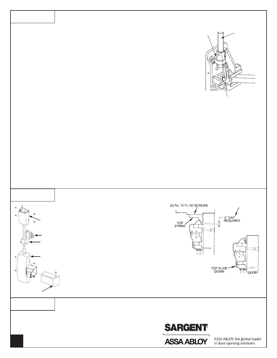
1. Verify that the rail assembly is not dogged (locked down).
2. Screw top rod (M) into top case (not shown) until finger tight.
Be careful not to cross thread.
3. Slide top rod (M) into adjustment tube (D). Do not pin in place.
4. Attach top case to the door where prepped in the first step.
Note: Top cases on fire rated wood doors must be throughbolted.
5. Visually align the hole in adj tube (D) with the lower hole on the
top rod (M). Then unscrew to extend top bolt out as much as possible.
Realign the two holes and insert rod adj pin (L).
6. Check for proper operation.
a) When door is closed, bolt and strike engagement should be 7/16" to 3/8"
b) When door is opened, rod should be held back, which means bolt
remains in the retracted position.
c) Top bolt should not disengage strike until rail is fully pushed in.
How to adjust for proper operation:
a.
Issue: Top bolt has very little engagement with top strike:
Solution: Top rod (M) must be lengthened by either: 1) unscrewing the top rod (M) from top case; 2) relocating the rod adjusting pin;
3) adding a shim under the strike to bring the strike closer; 4) repositioning top case closer to the strike.
b.
Issue: Top bolt will not disengage from strike, indicating too much engagement between top bolt and strike:
Solution: Top rod (M) must be shortened by either: 1) relocating the rod adj pin (L); 2) screwing the top rod (M)
into top case to shorten it.
c.
Issue: Top bolt will not go into hold back position, indicating too little engagement between top bolt and strike.
Door is opening before top bolt is retracted far enough to go into hold back position:
Solution: Top rod (M) must be lengthened by either: 1) unscrewing the top rod (M) from top case; 2) relocating the rod adjusting pin;
3) adding a shim under the strike to bring the strike closer; 4) repositioning top case closer to the strike.
d.
Issue: Push rail can not be dogged or pushed in completely, indicating that the top bolt has never been fully extended:
Solution: Top rod (M) must be lengthened by either: 1) unscrewing the top rod (M) from top case; 2) relocating the rod adjusting pin;
3) adding a shim under the strike to bring the strike closer; 4) repositioning top case closer to the strike.
ATTACHING TOP CASE AND ADJUSTING TOP ROD
FOURTH
(L) Rod
adjustment pin
(D) Adjusting tube
(M) Top rod
SIXTH
INSTALLING THERMAL PIN FOR 12-NB8700
12-NB8700 fire rated devices require the installation of a thermal pin assembly to maintain Fire Listing.
See Instruction Sheet A7436 for proper installation in wood and metal doors.
APPLYING GUIDE, COVERS AND END CAP
FIFTH
1. Confirm operation of exit device. Adjust rods
as needed.
2. Attach top and center chassis covers and end cap
as shown and secure with #8-32 oval head screws.
3. Locate rod guide and rod silencer at center of rod.
Rod must move freely in rod guide without rubbing.
4. For doors over 96": Install two (2) top rod guides
equally spaced between the top case and chassis
cover. Rod must move freely in guides.
Note:
Additional information for prefixes: AL-, 55, 56,
57, & 58, see appropriate instructions:
AL- prefix - A7224
55- prefix - A6808
56- prefix - A6876
57- prefix - A6810
58- prefix - A6835
Top case cover
Rod guide
Chassis cover
End cap
Copyright © 2008, 2010, 2012 Sargent Manufacturing Company,
an ASSA ABLOY Group company. All rights reserved.
Reproduction in whole or in part without the express written
permission of Sargent Manufacturing Company is prohibited.
A7617C
Note: Use two (2) No. 10 steel screws and mortise nuts
(when provided) in the position illustrated in the top chase.
Steel mortise nuts are twin knurled for identification.
NOTE: SHIM TOP STRIKE
WHEN NECESSARY TO
OBTAIN 1/8" GAP
Rod silencer