First, Determining center lines and prep door, Attaching nb-300 auxiliary control (if used) – SARGENT NB8700 Top Latch Surface Vertical Rod User Manual
Page 2
Copyright © 2008, 2010, 2012 Sargent Manufacturing Company,
an ASSA ABLOY Group company. All rights reserved.
Reproduction in whole or in part without the express written
permission of Sargent Manufacturing Company is prohibited.
A7617C
Horizontal
reference line
Vertical
reference line
Tape (supplied)
2
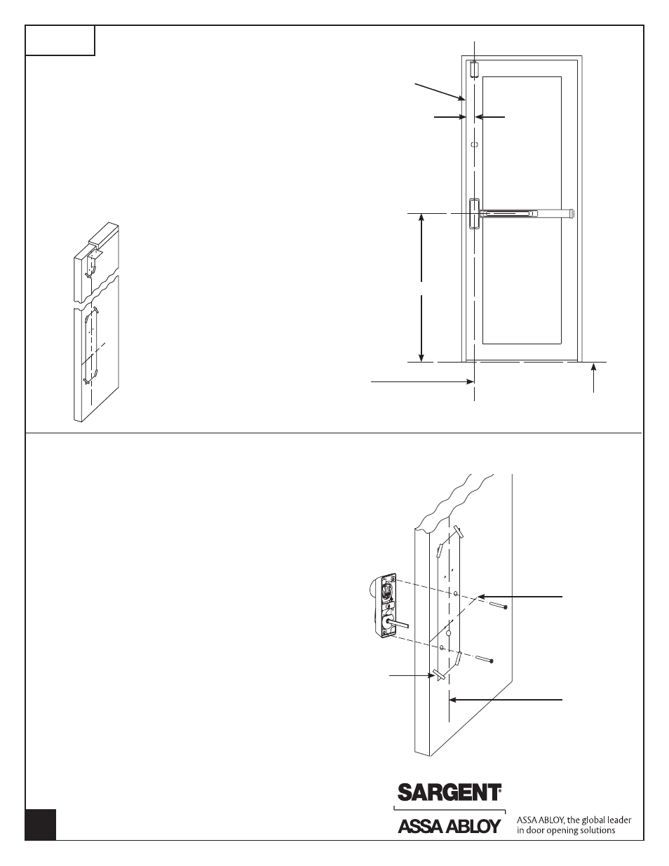
DETERMINING CENTER LINES
AND PREP DOOR
1. Determine dimension “A” to locate vertical reference line.
If lock stile is 4-1/2" wide or wider, “A” is 2-3/4".
If lock stile is less than 4-1/2", “A” is 1/2 of the exposed
width of the lock stile when the door is closed against the stop.
2. Standard rail centerline height is 41" above the finished floor.
3. Tape templates on inside of door along reference lines.
4. Spot and drill all holes from inside of door for exit and trim
being used.
5. For ET Controls, see templates supplied for trim.
Finished floor
“A”
41”
Vertical reference line
(centerline of chassis and top case)
Inside face
of door
FIRST
ATTACHING NB-300 AUXILIARY CONTROL (IF USED)
Note: This section is used only to install
NB-300 auxiliary control.
Note: NB-300 must be installed prior to installing
exit device on door.
1. Verify that the required 3 holes for NB-300
auxiliary control from template A7616 are
drilled and c’sunk. These holes should be
located from the inside of the door.
Note: Verify that NB-300 auxiliary control is
handed correctly. The top of the turn must
rotate toward door hinges.
2. Position NB-300 control on the outside of
the door with the cylinder up.
3. Throughbolt the NB-300 control to the door with
(2) # 10-24x2" long flat head screws and
tighten firmly.
4. Center case chassis is located with NB-300’s flat
spindle engaging lower hub of center case chassis
Frame edge