SARGENT LR8600 Low Profile Center & Top Latch Concealed Vertical Rod Exit Devices User Manual
Page 4
4
Copyright © 2009, 2010, Sargent Manufacturing Company, an ASSA ABLOY Group company.
All rights reserved. Reproduction in whole or in part without the express written permission
of Sargent Manufacturing Company is prohibited.
A7393D 3-10-10
H
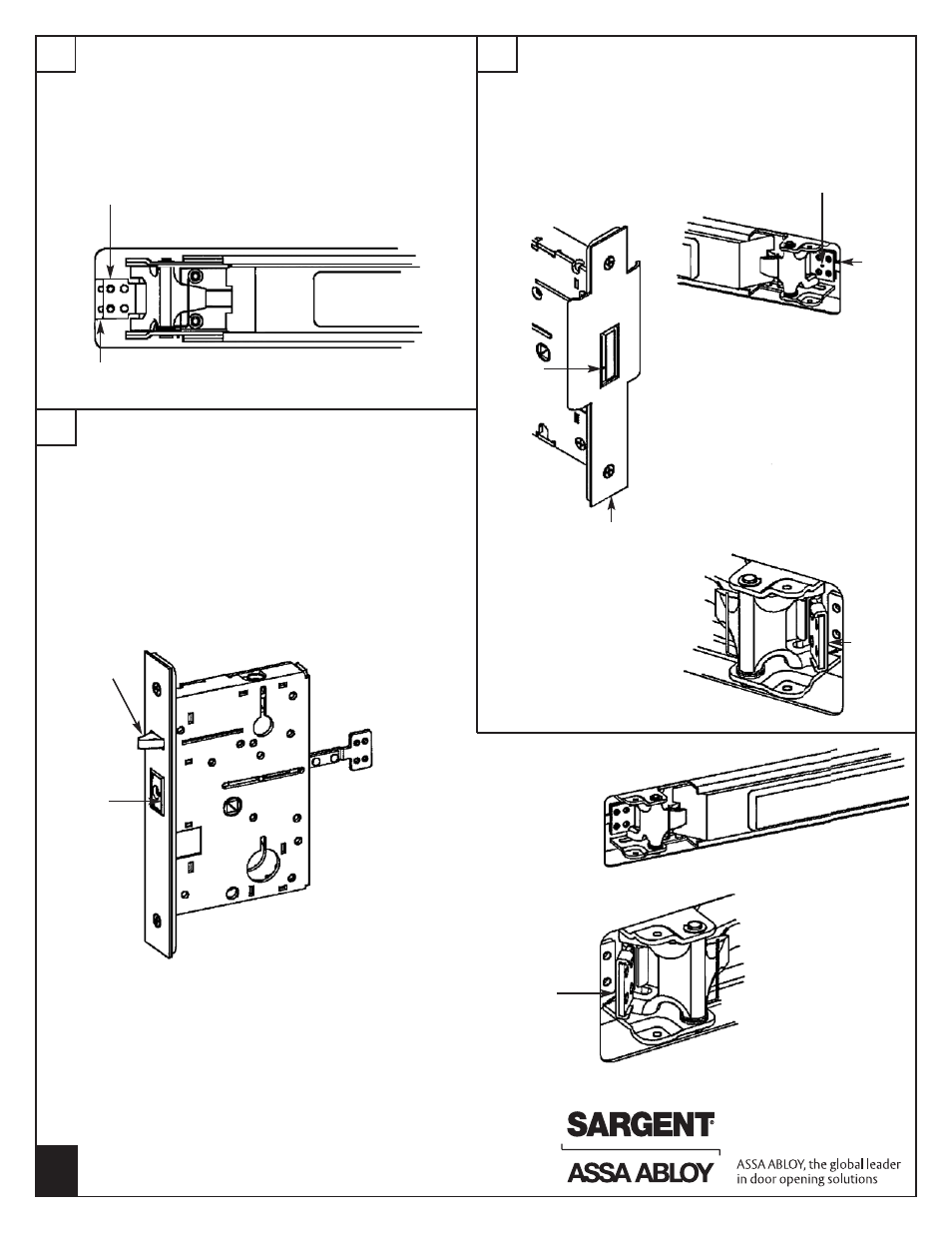
CONNECT LINKAGE
I
ADJUST SECONDARY MORTISE LOCK (LR8600)
1) Rotate link connector down and pull toward mortise lock.
2) Align one pair of holes on link connector with mortise tail and
secure using (2) #8 truss head screws.
REPEAT FROM PART “B” ON OPPOSITE DOOR.
Link
connector
1) Depress rail and observe center bolt. If bolt is projected, flush
or just beyond outside front, adjustment is correct.
2) If adjustment is required, remove (2) #8 screws from linkage.
3) Rotate lever trim to align next set of holes.
4) Reinstall the #8 screws and repeat step 1.
Mortise
tail
J
ADJUST PRIMARY MORTISE LOCK (LP8600)
1) With both doors closed, check for proper top and center
latchbolt throw and engagement with strikes.
2) Depress push rail to retract latches and open door. If center
bolt does not retract to clear the LR8600 outside front,
adjustment is required.
3) Remove (2) #8 screws from linkage.
4) Rotate lever trim to align next set of holes.
5) Reinstall the #8 screws.
6) Repeat step 1 to verify adjustment.
7) If binding condition occurs where top bolt remains retracted
and center bolt remains retracted when door closes, remove
the (2) #8 screws installed in part “H”.
8) Install link spacer between the link connector and mortise
tail. Reinstall #8 screws. Then repeat step 1.
5) If binding condition occurs where
top bolt remains retracted and
center bolt remains extended
when door closes, remove the (2)
#8 screws installed in part “H”.
6) Install link spacer between the link
connector and mortise tail, reinstall
#8 screws. Then repeat step 1.
Center
bolt
Link
connector
Mortise
tail
LR8600
outside front
Link
spacer
Link
spacer
Activation
bolt
Latchbolt