Final adjustment and regulating procedures – SARGENT 281 Series Cast Iron Closer User Manual
Page 3
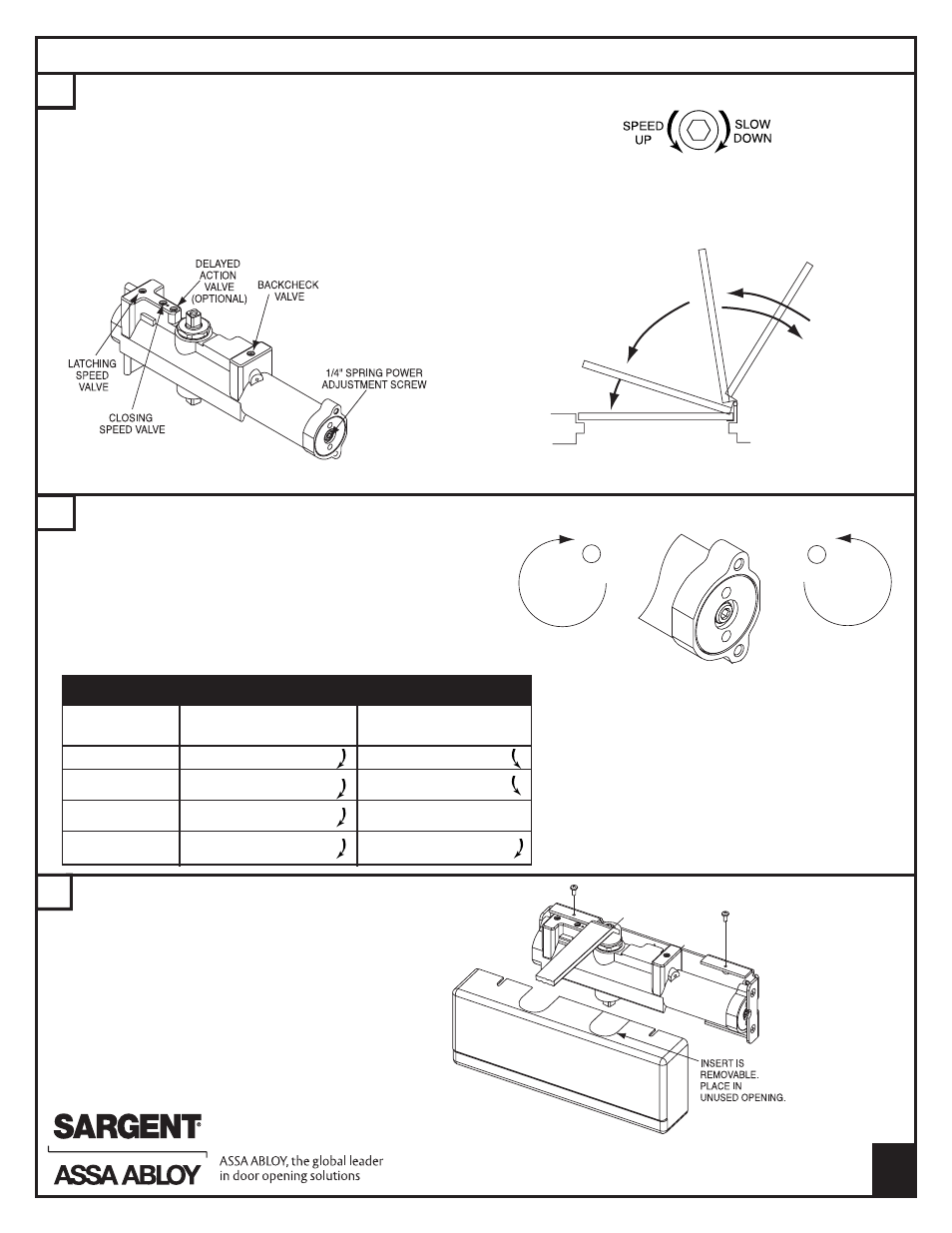
FINAL ADJUSTMENT AND REGULATING PROCEDURES
F
3
H
INSTALL COVER WITH TWO SCREWS AS SHOWN.
SSP INCLUDES HANDED METAL COVER
(NOT SHOWN) AND 6 LOBE SECURITY SCREWS.
G
Adjust Closing power to the minimum required to reliably
close and latch door
· If door is hard to open, decrease power slightly
· If door does not latch, increase power as required
· Use the chart below as a starting point
Doors adjusted with high closing power to overcome strong
draft conditions may exceed ADA standards
+
-
DOOR WIDTH
EXTERIOR DOORS
*INTERIOR DOORS
(INCHES)
24-30
Turn screw 2-7
Turn screw 1-5
30-36
Turn screw 7-11
Turn screw 3-6
36-42
Turn screw 11-15
FACTORY SET
42-48
Turn screw 15-17
Turn screw 8 & up
SPRING POWER ADJUSTMENT GUIDELINES
INCREASE
POWER
DECREASE
POWER
ADJUST CLOSING
POWER WITH A 1/4"
HEX WRENCH
· Adjust Door speed, and Latching speed valves to
achieve the desired closing time. Recommend 6
seconds minimum from 90° to the closed position.
· If Backcheck is required, adjust valve to achieve a
slight cushioning effect. Auxiliary stop required
· If closer is equipped with Delayed Action, regulate
valve to achieve the desired delay.
USE 1/8" HEX WRENCH
TO ADJUST VALVES
B
ACKCHECK
RANGE
D
ELAYED ACTION
RANGE
C
LOSING SPEED
RANGE
L
ATCHING SPEED
RANGE
Copyright © 2012, 2014, Sargent Manufacturing Company, an ASSA ABLOY
Group company. All rights reserved. Reproduction in whole or in part without the
express written permission of Sargent Manufacturing Company is prohibited.
A7921C