2a 3 1 – SARGENT 10 Line Cylindrical Lock User Manual
Page 2
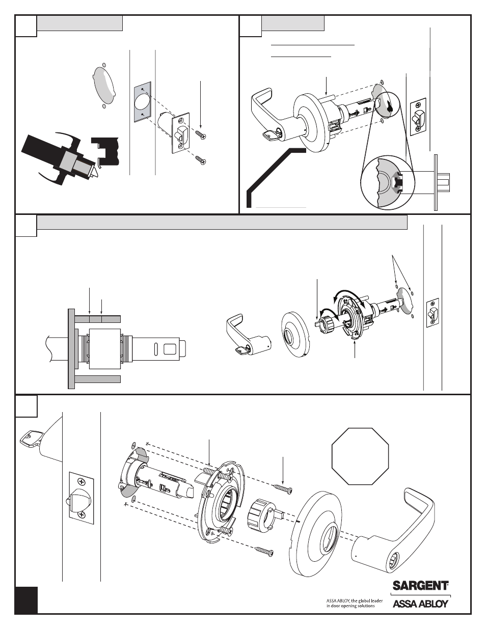
Preset Lock
Latch Installation
Door
frame
2-FRONT
Screws (2)
10-32 x 1-1/4"
Screws (2)
#6 x 3/4"
Scalp to be removed with flat
bladed screwdriver at notch
Test
for proper
operation
before
closing
door
Through-bolt
holes
Mounting plate
with through-bolts
Spacer bushing
2A
3
1
Preset thrubolt locations –
for different locations see
instructions to the right
Outside
of Door
Preset thrubolt locations –
for different locations see
instructions to the right
Outside
of Door
2
Install loosely;
tighten after step #3
Screws (2)
#8-32 x 3/4”
Please note: Doors without a beveled edge need to be
adjusted to center the latch - adjust per step 2A.
Outside
of Door
1-3/4" thick door
2" thick door
• Through-bolt Location – 12 and 6 o’clock
• Door Thickness – 1-3/4” thick
• See Step 2A for other door conditions
A7133J
© SARGENT Manufacturing Company
2
• Remove – outside lever (usually keyed), scalp and spacer bushing
• Rotate – mounting plate to either align with through-bolt holes in door
or adjust for proper door thicknesses (see markings on through-bolt)
• Reinstall – spacer bushing (to align with back of lever), scalp and lever
Through-bolt and door thickness adjustment other than preset