Keypad 10 line lock, Inside of door, Step #5 lock installation – SARGENT Keypad Cylindrical Locks User Manual
Page 9
7
A7113E • 800-810-WIRE (9473) • www.sargentlock.com
Keypad 10 Line Lock
8
/1
4
/0
8
C
o
p
yr
ig
h
t
©
2
0
0
5
,2
0
0
7
,2
0
0
8
,S
A
R
G
EN
T
M
a
n
u
fa
c
tu
ri
n
g
,a
n
A
S
S
A
A
B
LO
Y
G
ro
u
p
c
o
m
p
a
n
y.
A
ll
ri
g
h
ts
re
se
rv
e
d
.
R
e
p
ro
d
u
c
ti
o
n
in
w
h
o
le
o
r
in
p
a
rt
w
it
h
o
u
t
th
e
e
xp
re
ss
w
ri
tt
e
n
p
e
rm
is
si
o
n
o
f
S
A
R
G
EN
T
M
a
n
u
fa
c
tu
ri
n
g
is
p
ro
h
ib
it
e
d
.
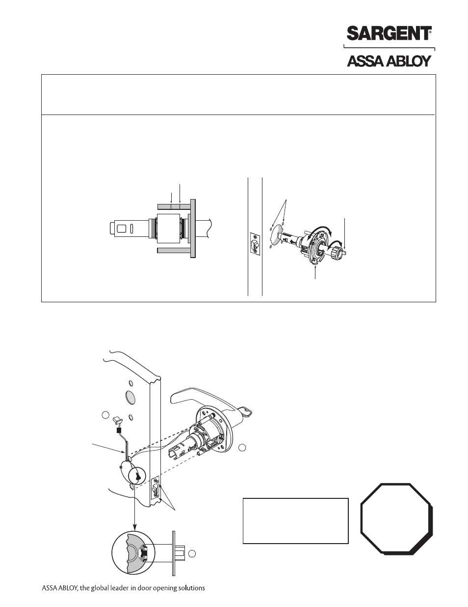
Screws partially
tightened
For wood
door only
Inside
of door
1
2
Lock Preset to:
• Through-bolt location– 12 & 6 o'clock
• Door thickness– 1-3/4" thick- see below for other door conditions
Adjustment for different through-bolt and door thickness:
• Remove outside lever (usually keyed), scalp and spacer bushing
• Rotate mounting plate to either align with through-bolt holes in door,
or adjust for proper door thicknesses (see markings on through-bolt)
• Reinstall spacer bushing (to align with back of lever) scalp and lever
Step #5 Lock Installation
IMPORTANT:
Door must remain open
during installation.
Use door stop.
3
1-3/4" thick door
2" thick door
Through-bolt
holes
Rotate to match
through-bolt holes in door
Spacer bushing
1. Feed wires into the lock body hole from outside of door
2. Install lock body into cross-bore hole from outside of the door (locked side)
3. Lock body must engage both the latch unit prongs and tail piece (as shown)
IMPORTANT:
Lockbody
must be
centered in
the door.