Winchester Repeating Arms 101 User Manual
Page 9
6
7
25 we reserve the right to reFuse service on
FirearMs that have been altered, added to
or substantially changed.
Removal of metal from the barrel, or modifications
of the firing mechanism and/or operating parts, may
lead to a refusal of service on such firearms. We will
charge you for parts and labor to return the firearm to
original specifications.
do not, under any circuMstances, alter
the trigger, “saFety” or other Parts oF the
Firing MechanisM oF this or any other
FirearM. Failure to obey this warning
May result in injury or death to yourselF
or others.
b e c a r e F u l !
g
eneral
D
eScription
anD
o
peration
Balance. Pointability. Reliability. Handling. These are
qualities you expect in an over and under, and they’re
what you’ll get with your Model 101. It’s superbly
designed, combining the traditions of American hunting
guns and European competition guns. These shotguns
provide a lively feel, with dimensions designed to allow
you to quickly move to your target. The low-profile
receiver with dual, between-the-barrel lockup is the
foundation, and combined with ideal stock dimensions,
put you on target consistently.
The Model 101 is an over and under shotgun made to fire
two successive shots by pulling the trigger twice, once for
each shot. Each time the action is opened after firing the
hammers are cocked automatically and empty shells (one
or two) are ejected clear of the chamber(s) automatically.
Unfired shells are elevated in the chambers. The action is
opened with a lever mounted on the top of the receiver
just forward of the “safety”/selector. The shotgun breaks
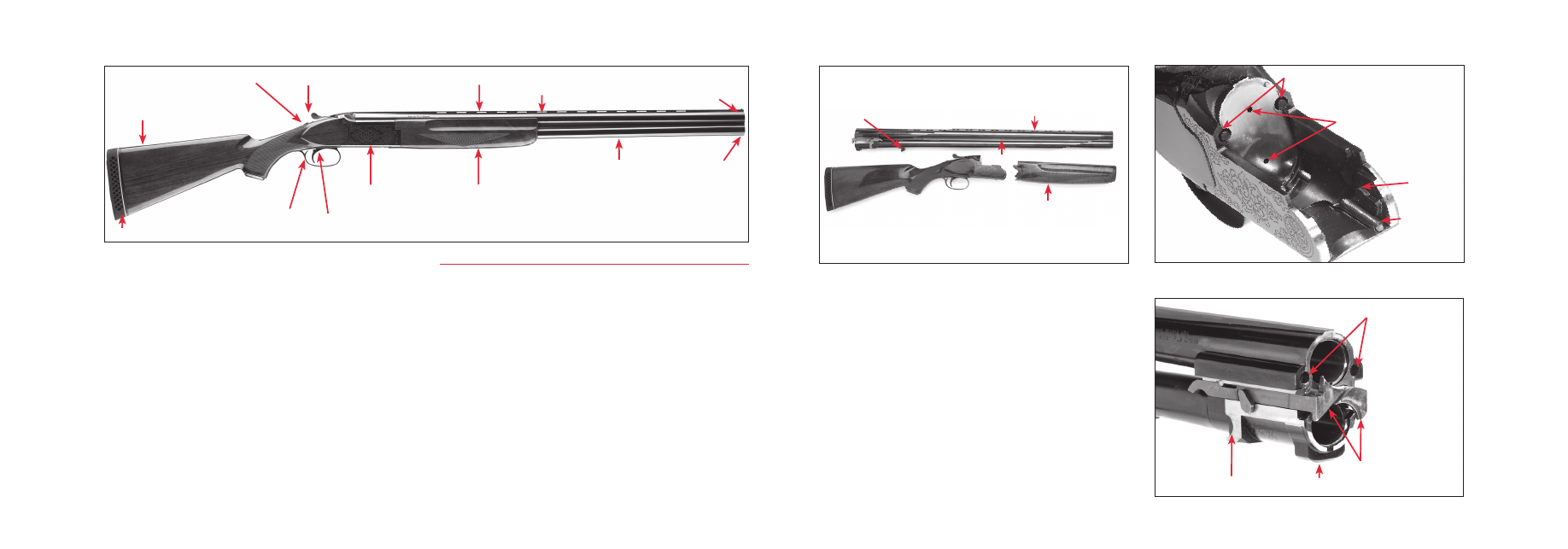
down into three pieces for cleaning or storage (Figure 2).
Prior to using live ammunition, familiarize yourself
thoroughly with all the operating instructions in this
owner’s manual. Get accustomed to the feel of your new
firearm. Know the forces required to operate the action.
Understand how to select the firing order of the barrels.
Learn how to pull the trigger correctly, and above all,
know the location and operation of the “safety”/selector.
Procedures for disassembly and operation of various
components are outlined in the following sections. Please
read and study them thoroughly.
FIGURE 2
Forearm Release
Latch Lug
Ventilated Rib
Side Rib
Forearm Release Latch
FIGURE 1
Top Lever
Trigger
Forearm
Muzzles
Barrels
Action/Receiver
Front Sight
Recoil Pad
Trigger Guard
Buttstock
Ventilated Rib
Mid-Bead Sight
(Special Models)
“Safety”/Selector Switch
FIGURE 3
Locking Pins
Cocking Lever
Trunnion
Firing Pins
FIGURE 4
Locking Pin Recesses
Locking Lug
Trunnion Surface
Ejectors/Extractors
(Continued on page 10.)