Quick robotic torch, 02 disassembly, 03 changing the cartridge kit – Tweco Quick Robotic Torch User Manual
Page 12
3-8
Quick Robotic toRch
SM-QRTORCH
INSTALLATION AND DISASSEMBLY
23. Plug or wire the other end into the proper pin locations on
the robot. Refer to the manufacturer recommendations
and installation instructions.
24. If the torch being installed is a water-cooled QRW or QRWA
series, a water supply providing not less than ¾ gallons/
minute (2.84 liters/minute) water flow must be used
during operation. The water supply should be installed
to run when the power source is turned “on” if possible
to avoid any damage to the torch and cable assembly.
CAUTION
Operating a water-cooled torch and cable
assembly without water or restricted flow will
result in damage to the cable assembly.
25. The torch and cable assembly is furnished with a purge
hose that can be used to supply inert gas and or anti-
spatter through the torch block and conductor tube
assembly. To use this purge hose, remove the plastic plug
and connect accordingly.
26. The torch is now ready to place into operation. Be sure to
check the TCP and single step the robot through the robot
program to ensure that the conductor tube positioning is
correct.
3.02 Disassembly
1. To disassemble the torch and cable assembly from the
robot arm, reverse the steps noted in Section 3.01
3.03 Changing The Cartridge Kit
1. To remove and replace the correct cartridge kit, follow the
steps below:
(a) Cut the metal straps holding the outer cover in place on
both ends.
(b) Pull the protective outer cover away from the cable
assembly.
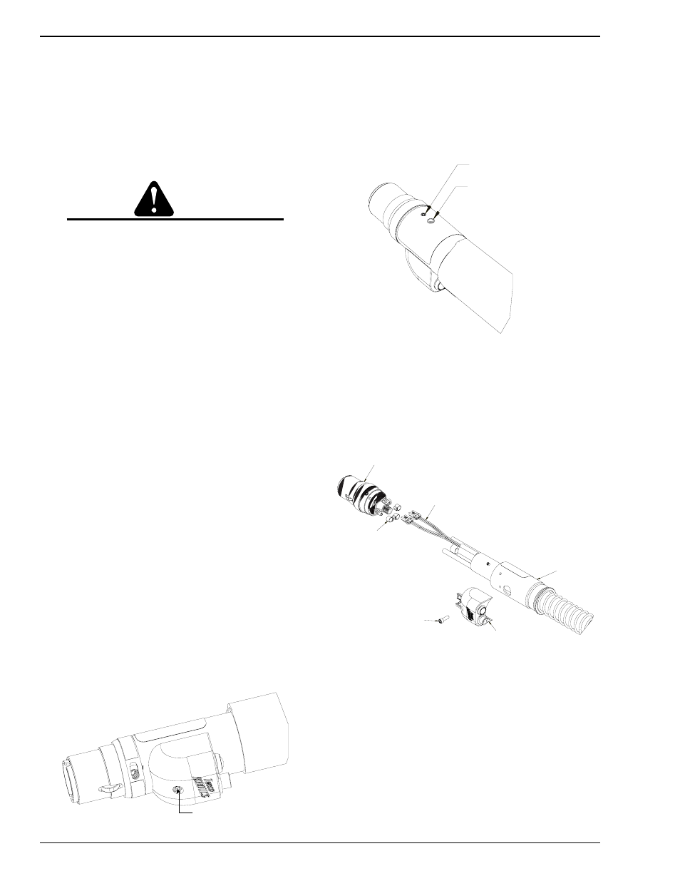
(c) Remove the socket head cap screw located on the molded
inch switch housing. Once the housing is loose and can
be pulled away from the front sleeve cover, pull apart the
two exposed electrical connections. Refer to Figure 3-8
SOCKET SET SCREW
Art # JB-00020
Figure 3-8: Removal of Inch Switch Housing
(d) With the housing away from the front sleeve cover,
insert the factory-supplied 3/32” Allen wrench into the
two (2) access holes for the set screws and loosen. A
third set screw will need to be loosened along with the
two mentioned. This set screw is located 180° from
the molded housing screw hole and approximately
½” (12,7mm) below the “Conduit Set Screw” hole
noted on the label. Refer to Figure 3-9.
ACCESS HOLE FOR SET SCREW
CONDUIT SET SCREW HOLE
Art # JB-00021
Figure 3-9: Access Hole for Set Screw
(e) Push the 3/32” Allen wrench through the label and
insert the set screw and loosen.
(f) Slide the front sleeve cover and support spring away
from the cartridge kit. Refer to Figure 3-10.
FRONT SLEEVE COVER
& SPRING
INCH SWITCH HOUSING
SOCKET HEAD
CAP SCREW
ELECTRICAL CONNECTIONS
HOSE CLAMPS
CARTRIDGE
KIT
Art # JB-00022
Figure 3-10: Exploded View of Torch
(g) Remove the heat shrink and clamp holding the inch
switch cable to the cablehoz.