Quick robotic torch, 01 installation – Tweco Quick Robotic Torch User Manual
Page 10
3-6
Quick Robotic toRch
SM-QRTORCH
INSTALLATION AND DISASSEMBLY
SECTION 3:
INSTALLATION AND DISASSEMBLY
3.01 Installation
1. Remove the torch and cable assembly from the carton,
and lay the assembly in a straight and untwisted position
on a workbench or floor.
2. Verify that the overall cable length is correct to fit between
the feeder - robot torch mount combination.
NOTE
For cable assemblies longer than 5ft. (1,52m), it
is recommended incorporating a spring-loaded
stabilizer bar/balancer to the robot work cell to
provide support to the center of the cable assembly.
This will eliminate both excessive drooping of the
cable assembly and any interference with the
fixtures and tooling in the work area.
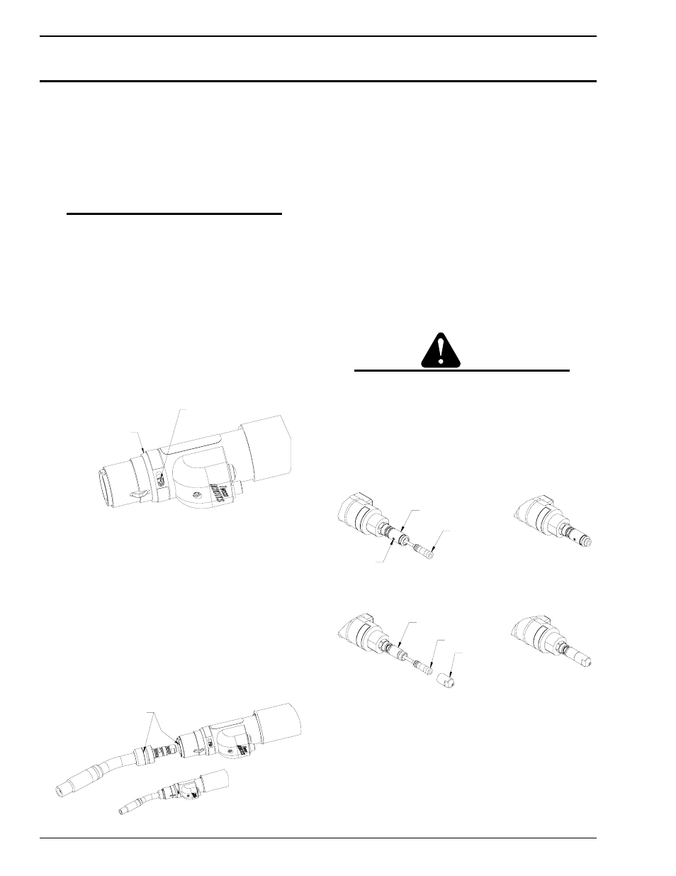
3. Rotate the front sleeve cover to expose the stainless steel
set screw located in the torch block assembly. Insert the
factory supplied 5/32” T-handle Allen wrench into the set
screw and rotate counterclockwise until it stops as shown
in Figure 3-1.
ROTATE FRONT SLEEVE COVER
TO EXPOSE SET SCREW. ROTATE
COVER TO CONCEAL SET SCREW
PRIOR TO TORCH OPERATION.
SET SCREW
(5/32" ALLEN KEY)
Art # JB-00025
Figure 3-1: Conductor Tube Locking Set Screw
4. Insert the conductor tube assembly into the torch block
assembly. The conductor tube is positively located into
the torch body by the use of two stainless steel alignment
pins.
5. Push the conductor tube assembly into place until the
stainless steel set screw can drive the back plug on the
conductor tube into its locked operating position. The
conductor tube has a machined locating groove around
its rear diameter. This groove will be flush with the front
housing when properly installed as shown in Figure 3-2.
WHEN CONDUCTOR TUBE IS FULLY SEATED,
GROOVE ON TUBE SHOULD LINE UP WITH
EDGE OF INSULATING SLEEVE.
Art # JB-00026
Figure 3-2: Conductor Tube Installation
6. Remove the gas diffuser, tip and nozzle from the conductor
tube assembly.
7. The torch and cable assembly comes with the Miller
®
rear
connector plug installed. If the feeder requires a different
rear connector plug, select the correct rear connector plug
for the feeder being used and thread the plug into the rear
of cable assembly. This connection should be wrench
tight.
8. The QR Series torch and cable assemblies are furnished
with R45-116 conduit and the rear connector plugs to
fit this series of conduit. If a different conduit and rear
connector plug is required, refer to Page 9-31 listing the
various conduits that are available.
9. Remove the conduit from the package and uncoil
carefully.
CAUTION
Bending or distorting the conduit can cause wire
feed problems.
10. Loosen the set screw located on the Tweco
®
, Panasonic
®
and Lincoln
®
rear connector plug to ensure the conduit will
feed through properly. For Miller
®
style plug, remove the
threaded connector plug nipple from the rear connector
plug on the torch assembly. Refer to Figure 3-3 & 3-4.
SET SCREW
TWECO PLUG
CONDUIT ASSEMBLY
Art # JB-00010
Figure 3-3: Conduit Installation with Set Screw
MILLER PLUG
CONDUIT ASSEMBLY
PLUG NIPPLE
Art # JB-00011
Figure 3-4: Conduit Installation with Plug Nipple (Miller
®
Style)
11. Insert the factory-supplied 5/32” T-handle Allen wrench
through the hole on the aluminum front handle cap,
identified as “Conduit Set Screw” on the label, and rotate
the set screw counterclockwise until it stops rotating.