Quick robotic torch – Tweco Quick Robotic Torch User Manual
Page 11
3-7
Quick Robotic toRch
SM-QRTORCH
INSTALLATION AND DISASSEMBLY
12. Insert the exposed raw coil end of the conduit, factory
supplied, into the rear connector plug. Feed the conduit
through the gun and conductor tube assembly. If the
conduit attempts to hang up, rotate the conduit liner
counterclockwise while gently pushing.
13. When the conduit is completely through the torch and
conductor tube assembly, seat the brass conduit stop
firmly against the connector plug.
14. Tighten the set screw on the Tweco
®
, Panasonic
®
, and
or Lincoln
®
rear connector plug. For Miller
®
style rear
connector plug, re-install the threaded connector plug
nipple. This connection should be wrench tight.
15. Re-insert the factory-supplied 5/32” T-handle Allen
wrench into the hole for the “Conduit Set Screw” on the
front handle cap and rotate the set screw clockwise. The
set screw should be hand tight. Refer to Figure 3-5.
CONDUIT SET SCREW HOLE
Art # JB-00012
Figure 3-5: Access Hole for Conduit Set Screw
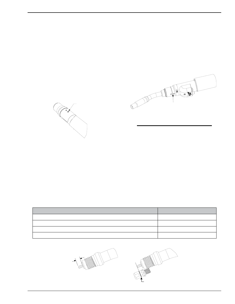
16. Trim the conduit extending from the front of the conductor
tube assembly by following the steps below:
Method “A” – Using a tape measure or scale, mark and cut the
conduit to the cut length noted in the table below. Refer
to Figure 3-6 — Method “A”.
Method “B” – The diffusers have a machined groove around
the outer diameter. Position the diffuser as shown in Figure
3-6 — Method “B” and mark and cut the conduit.
17. After trimming to length, remove any obstructions from
the end of the conduit radius.
18. Re-install the diffuser, tip and nozzle into the conductor
tube assembly.
19. Loosen the robot mount arm connection on the robot arm,
and insert the cartridge kit of the torch and conductor tube
assembly into position on the robot arm. The keystock
located on the cartridge kit should be placed into the
mating slot on the mount arm until the sleeve bottoms
against the robot arm. Re-tighten the connection to secure
the assembly in place. Refer to Figure 3-7.
KEYSTOCK
ART # JB-00031
Figure 3-7: Locating Keystock
NOTE
For cable assemblies longer than 5ft. (1,52m), it
is recommended incorporating a spring-loaded
stabilizer bar/balancer to the robot work cell to
provide support to the center of the cable assembly.
This will eliminate both excessive drooping of the
cable assembly and any interference with the
fixtures and tooling in the work area.
20. Install the rear connector plug into the feeder.
21. Install the E-stop Cable between the robot deflection mount
and the cable front housing on the torch.
22. Attach an adapter cable, sold separately, to the rear
connection on the yellow E-stop cable located at the rear
of the cable assembly. Refer to Section 4 for detail on
optional adapter cables and wiring instructions.
Conductor Tube Assy.
Cut Length “A”
QTR66 Series – (For use with QRA series torch/cable assemblies)
1-5/16” (33,32mm)
QTRW63 Series – (For use with QRW & QRWA series torch/cable assemblies)
15/16” (23,80mm)
QTRW64 Series – (For use with QRW & QRWA series torch/cable assemblies)
1/4” (6,35mm)
QTRW66 Series – (For use with QRW & QRWA series torch/cable assemblies)
5/16” (7,92mm)
CUT LINE
A
”
B
“
D
O
H
T
E
M
”
A
“
D
O
H
T
E
M
Art # JB-00013
Figure 3-6: Conduit Cut Length