03 feedhead components, 03 feedhead components -4, Ultrafeed va 4000s – Tweco VA 4000S Ultra-Feed User Manual
Page 30
ULTRAFEED VA 4000S
OPERATION
4-4
Manual No. 0-5135
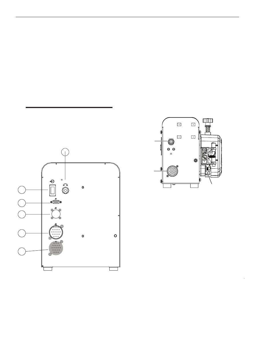
13.CAN INTERFACE PORT (J2): This connection allows
the ULTRAFEED VA 4000 S to communicate with other
select Thermal Arc power sources. This is available
with the advanced interface kit.
14.SERIAL PORT (J1): This connection allows the
ULTRAFEED VA 4000 S to communicate with a
personal computer. This feature is available with the
advanced interface kit.
15.POWER ON/OFF SWITCH: This switch controls only
the wire feeder and not the power source.
16.CIRCUIT BREAKER: This breaker protects the unit
from electrical faults.
NOTE
If the circuit breaker trips, it turns the power
switch to the OFF position. A short cooling
period must be allowed before an attempt is
made to reset the unit by pressing the circuit
breaker reset switch.
11
12
13
14
15
16
Art # A-09223
A
M
L
K
U
N
B
C
P
V
T
J
H
S
R
D
E
F
G
A
M
L
K
U
N
B
C
P
V
T
J
H
S
R
D
E
F
G
Figure 4-4: Rear Panel Controls and Connections
18.GAS VALVE INLET: This is where the shielding gas
hose is connected to the wire feeder. The gas valve
inlet controls the “on/off” flow of shielding gas through
the welding gun.
19.32' CONTROL CABLE PLUG: The 32' control cable
connects to the VA 4000 S Separation wire feeder/
motor to this 19-pin amphenol connector plug(of
which 14 pins are used). It contains the signals
required to allow the welding power source, controller
and the wire feeder to work together as a system. Refer
to Previous Chart and figure 4-2 and 4-5.
20.WELD CABLE CONNECTION: This is where the power
source welding cable is connected to the feeder. Make
sure this connection is tight or arcing could occur.
Art # A-09225
18
19
20
Figure 4-5: Separation Motor Connections
4.03 Feedhead Components
21.INPUT GUIDE LOCKSCREW: Tighten this lockscrew
to secure the input wire guide.
22.SPRING TENSION KNOB: Use the spring tension knob
to adjust the amount of force the feed rolls exert on
the welding wire.
23.FEEDROLL GEAR / KNOB : This knob is used to secure
the feedroll to the pressure arm. Rotate the knob to
change the feedroll.
24.PRESSURE ARM: This arm pivots off the front of the
feedhead to allow access to the wire guides and wire
path.
25.CENTER GUIDE LOCKSCREW: Tighten this lockscrew
to secure the center wire guide.
26.OUTPUT GUIDE LOCKSCREW: Tighten this lockscrew
to secure the output wire guide.