10 feedrolls, 10 feedrolls -8 – Tweco 180 Portable MIG User Manual
Page 32
FABRICATOR 140, 180
INSTALLATION
Manual 0-4991
3-8
July 20, 2007
1
5
6
2
3
4
Art # A-07906
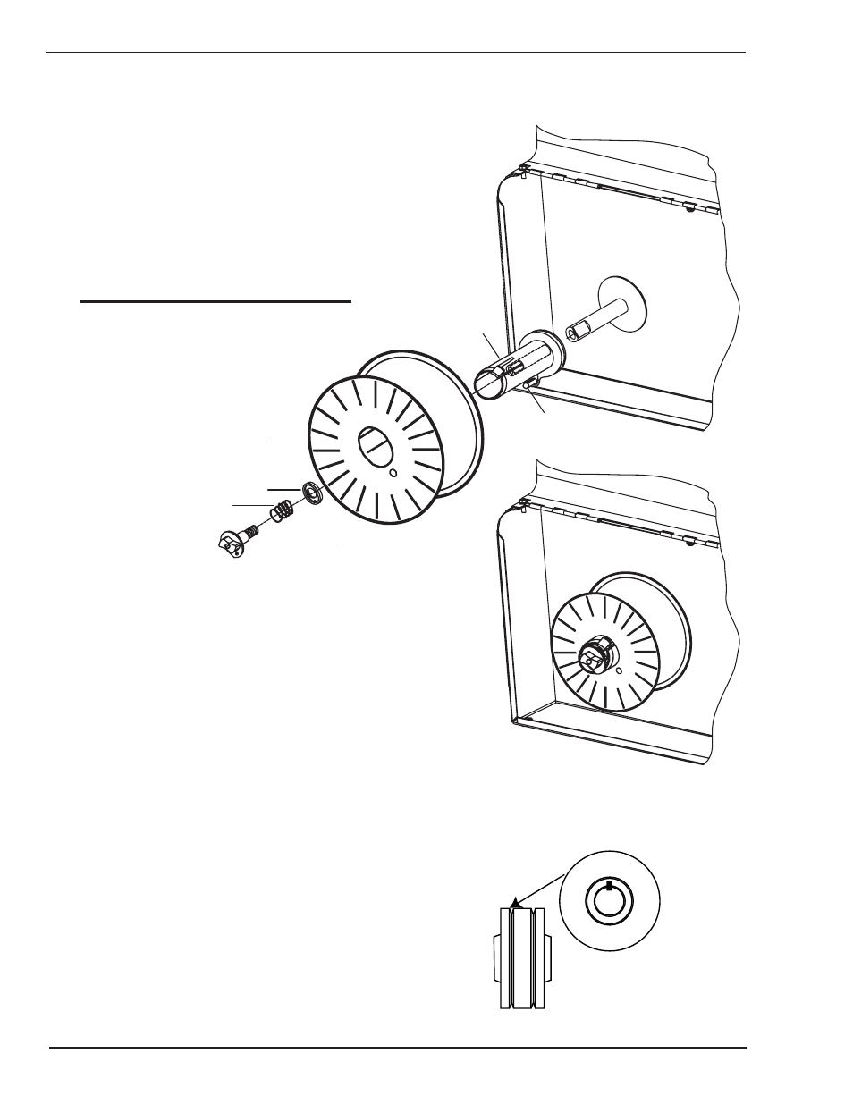
Installation of 8” (203mm) spool
Assemble parts in sequence (shown in Figure 3-7).
1. Spool 8” (203mm)
2. "D" Washer
3. Retaining Spring
4. Nut
5. Spool Adapter Hub
6. Drive Pin
NOTE
Nut is tightened until a slight force is required
to turn the spool
3.10 Feedrolls
A feedroll consists of two different sized grooves. As
delivered from the factory, the drive roll is installed for
.023” (0.6mm) for the Fabricator 140, and .030” / .035”
(0.8mm / 0.9mm) for the Fabricator 180.
The groove size visible when fitting the feedroll is the
groove size in˜use.
The groove closest to the motor is the one to thread.
This also applies to optional feedrolls which are available
for this machine.
.030
0.8
Art # A-07963
Figure 3-8: Feedroll Example
Figure 3-7: 8" Spool Installation